_ V1.
Contents Contents.............................................................................................................................. 2 Introduction ......................................................................................................................... 3 Description .......................................................................................................................... 3 View of the ITLPC2138 ......................................................................
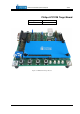
Introduction Philips LPC2138 Target Board is an evaluation and a development system for Philips ARM7TDMI-S based LPC2138 microcontroller. The ITLPC2138 package consists of a USB cable and a target board populated with Philips LPC2138 CPU, minimum peripherals, JTAG debug connector, ETM trace connector and an on-board integrated iSYSTEM debugger. The user can write and debug the application using the on-board integrated iSYSTEM debugger, which connects to the PC through the USB connection.
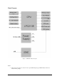
Block Diagram Figure 3: ITLPC2138 Block diagram Notes 1. The board provides 16-pin connector for the optional LCD display (type CMC216x04), which is not included in the package.
Components List Name P1 P2 P3 P4 P5 J1 J2 J3 J4 J5 J6 J7 - J10, J15 – J20, J22,J25 J11 J12 J13 J14 J21 LD0 – LD3 LD11 LD12 T0 – T3 Reset TRIM-PT © iSYSTEM, December 2005 Description Connector for manufacturing purpose ETM Trace connector JTAG debug connector USB connector (integrated debugger) DB9 connector, serial port (UART1) Expansion connector GPIO pins P0.0 – P0.7 Expansion connector GPIO pins P0.8 – P0.15 Expansion connector GPIO pins P0.16 – P0.23 Expansion connector GPIO pins P0.25 – P0.
Power Supply The target board is powered from the PC USB port, through which winIDEA (IDE) running on a PC, connects to the on-board integrated debugger. Connection is made using a standard USB cable. Battery power supply for RTC can be optionally connected to J11 (see J11 description for more details). Jumper & Connector Descriptions • J7: Trace Port Enable: J7 is set to enable pins P1.25:16 to operate as ETM Trace port after reset. Default not set. • J8: Debug Port Enable: J8 is set to enable pins P1.
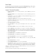
Connectors DB9 male connector UART1 (P5) Pin No. 2 3 5 Symbol RxD TxD GND The serial port is configured as a standard 3-wire interface. Cross female to female cable is needed for connection with PC computer COM port. 3-pin serial connector UART0 (J14) Pin No. 1 2 3 Symbol RxD TxD GND The serial port is configured as a standard 3-wire interface.
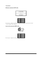
16-pin LCD connector (J21) Top View Pin Assignment for Crystal Clear technology CMC216x04 LCD Pin No.
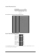
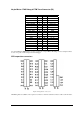
38-pin Mictor JTAG Debug & ETM Trace Connector (P2) Signal Not used Not used GND Not used CPU_RESET CPU_TDO GND CTCK CPU_TMS CPU_TDI CPU_TRST GND GND GND GND GND GND GND GND Pin 1 3 5 7 9 11 13 15 17 19 21 23 25 27 29 31 33 35 37 Pin 2 4 6 8 10 12 14 16 18 20 22 24 26 28 30 32 34 36 38 Signal Not used Not used TRACECLK Not used Not used T3V3 Not used GND GND GND GND P1.19 P1.18 P1.17 P1.16 P1.20 P1.23 P1.22 P1.21 An external JTAG & ETM debug tool can be connected to a 38-pin Mictor P2 debug connector.
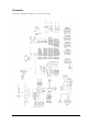
Schematic Note: On-board integrated debugger is not part of the schematic.
Licensing the on-board integrated debugger A 30-days evaluation period starts after the debugger (winIDEA) connects to the ITLPC2138 for the first time. Within the evaluation period, the user should request a regular license from iSYSTEM. Run the request wizard to obtain the license INIT string by pressing the ‘Request INIT…’ button in the ‘Hardware/Hardware/License’ tab.
Use of the on-board integrated debugger Follow below instructions, in order to get a sample application running with “out of the box” experience. All jumpers are set in the default position during the final tests in the manufacturing. If winIDEA 2006 CD is not part of the package, please obtain winIDEA 2006 setup from your local iSYSTEM office or from www.isystem.com.
Use of an external debugger An external debugger can be: • a JTAG debugger, which connects to a 20-pin P3 connector • a development tool supporting JTAG debugging and ETM (on-chip trace), which connects to a 38-pin Mictor P2 connector Setting up a debug environment for the first time • Verify jumpers J15-J20 (see Jumpers description for their default position) • Verify that jumper J8 is set • Verify that jumper J7 is set if your development tool connects to P2 • Verify that jumper J9 is set in po
Troubleshooting The flash boot loader code is executed every time the CPU is powered or reset. The loader can execute the ISP command handler or the user application code. P0.14 is sensed on a rising edge on the RST (CPU reset) pin. If a low level is detected, ISP command handler starts and takes over control of the CPU after reset. If there is no request for the ISP command handler execution (a high-level detected), a search is made for a valid user program.
Notes: © iSYSTEM, December 2005 15/16
Disclaimer: iSYSTEM assumes no responsibility for any errors which may appear in this document, reserves the right to change devices or specifications detailed herein at any time without notice, and does not make any commitment to update the information herein. © iSYSTEM. All rights reserved.