Kvaser LAPcan / LAPcan II Hardware Guide Copyright 2001-2006 Kvaser AB, Mölndal, Sweden http://www.kvaser.com Last updated Monday, 06 November 2006 We believe that the information contained herein was accurate in all respects at the time of printing. Kvaser AB cannot, however, assume any responsibility for errors or omissions in this text. Also note that the information in this document is subject to change without notice and should not be construed as a commitment by Kvaser AB.
Kvaser LAPcan / LAPcan II Hardware Guide (This page is intentionally left blank.) Kvaser AB, Mölndal, Sweden — www.kvaser.
Kvaser LAPcan / LAPcan II Hardware Guide 3(19) 1 Table of Contents 1 Table of Contents ........................................................................................................................ 3 2 About this manual ....................................................................................................................... 4 3 Introduction...................................................................................................................................
Kvaser LAPcan / LAPcan II Hardware Guide 4(19) 2 About this manual This manual is intended for the Kvaser LAPcan/Kvaser LAPcan II users. This manual contains a description of the hardware’s properties and general instructions for connecting the device to a computer. Kvaser AB, Mölndal, Sweden — www.kvaser.
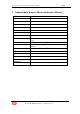
Kvaser LAPcan / LAPcan II Hardware Guide 5(19) 3 Introduction Table 1: The Kvaser LAPcan/LAPcan II devices and their EAN numbers. Device Product Number Kvaser LAPcan 733-0130- 00029-2 Kvaser LAPcan II 733-0130- 00115-2 Kvaser LAPcan is a PC card compliant with the PC-Card (PCMCIA) standard. It contains the powerful microcontroller C161O from Infineon and two SJA1000 CAN controllers from Philips. The SJA1000 handles CAN messages with 11 bit as well as 29 bit identifiers.
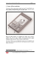
Kvaser LAPcan / LAPcan II Hardware Guide 6(19) 4 Kvaser LAPcan installation The Kvaser LAPcan card may be inserted in any free PC Card (PCMCIA) slot that is capable of accommodating Type II or Type III cards. You don’t have to switch the power off before inserting or removing the card. 1 2 Figure 1. A Kvaser LAPcan with its two CAN ports. Many new laptop computers are equipped with CardBus slots instead of PCMCIA slots.
Kvaser LAPcan / LAPcan II Hardware Guide 7(19) 5 Technical data, Kvaser LAPcan and Kvaser LAPcan II CAN channels 2 (CAN 2.0A and 2.0B active) CAN Transceivers The transceivers are integrated into the DRVcans. CAN Controllers Philips SJA 1000 Microcontroller Siemens SAB-C161O (16 MHz) Baudrate 5 kbit/s ...
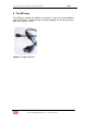
Kvaser LAPcan / LAPcan II Hardware Guide 8(19) 6 The DRVcans The DRVcans contain the CAN bus transceiver. There are several different types of DRVcans, and which one to choose depends on the physical layer your CAN system is using. Figure 2. A typical DRVcan. Kvaser AB, Mölndal, Sweden — www.kvaser.
Kvaser LAPcan / LAPcan II Hardware Guide 6.1 9(19) DRVcan Types Currently available DRVcans include: Name DRVcan 251 DRVcan 1053 DRVcan 1054 DRVcan 1054 Opto DRVcan DNopto DRVcan S DRVcan S Opto DRVcan Fi HS DRVcan Fi LS DRVcan Fi SWC DRVcan LIN DRVcan T&T DRVcan EVA Customer specific Industry-standard highspeed 82c251 transceivers; DSUB connector according to the CiA standard. Industry-standard lowspeed TJA1053 transceivers; DSUB connector according to the CiA standard.
Kvaser LAPcan / LAPcan II Hardware Guide 6.2 10(19) How to use the DRVcan • • Push firmly to insert the connector on the DRVcan into Kvaser LAPcan. To remove the connector, push both tabs (see Figure 3 below) as deep as possible and pull out the connector. • We recommend that you remove the card before inserting or removing DRVcans. This is because not all software will be able to handle a “hotswap”.
Kvaser LAPcan / LAPcan II Hardware Guide 11(19) 7 A Few Words of Caution • • • • Do not apply excessive force when inserting the card into the computer. Do not remove the card by pulling on the I/O cables. Always make sure the I/O connectors are firmly seated. When you remove a DRVcan, you must firmly press both the tabs (see Figure on the connector. 3 below) Figure 3. The I/O connector on a DRVcan. The tabs are marked with arrows. The D-SUB connector Figure 4. The DSUB connector on a DRVcan.
Kvaser LAPcan / LAPcan II Hardware Guide 12(19) Caution! Always connect the ground pin on the D-SUB to the ground of your CAN bus. Some laptop computers have AC power supplies that might destroy the DRVcan unless it is properly grounded. Running the laptop from battery power is usually OK even if the ground lines are not connected. Kvaser AB, Mölndal, Sweden — www.kvaser.
Kvaser LAPcan / LAPcan II Hardware Guide 8 DRVcan configuration The DRVcan -251, -1053, and -1054 types have the following pin configuration: D-SUB pin Colour code Function number 1 N/A Not connected. 2 Green CAN_L (low level @ dominant) 3 Brown GND 4 Orange Reserved, do not connect. 5 Black Shield 6 N/A Not connected. 7 Red CAN_H (high level @ dominant) 8 N/A Not connected. 9 Yellow Not connected. Pins 2, 3, 4, and 7 are protected by 250 mA fuses.
Kvaser LAPcan / LAPcan II Hardware Guide The DRVcan Fi HS has the following pin configuration: D-SUB pin number 1 Colour code Function N/A Not connected. 2 Green CAN_L (low level @ dominant) 3 Brown GND 4 Orange Not connected. 5 Black Shield 6 N/A Not connected. 7 Red CAN_H (high level @ dominant) 8 N/A Not connected. 9 Yellow External power, 6-36V. The DRVcan Fi LS has the following pin configuration: D-SUB pin number 1 Colour code Function N/A Not connected.
Kvaser LAPcan / LAPcan II Hardware Guide 7 Red CAN_H (high level @ dominant) 8 N/A Not connected. 9 Yellow External power, 6-36V. 15(19) Here is the pin configuration for the DRVcan-S: D-SUB pin number 1 Colour code Function N/A Not connected. 2 Green Not connected. 3 Brown GND 4 Orange Reserved, do not connect. 5 Black Shield 6 N/A Not connected. 7 Red CAN_H (high level @ dominant) 8 N/A Not connected.
Kvaser LAPcan / LAPcan II Hardware Guide 16(19) 8.1 Technical Data for DRVcan 251 Transceiver type Philips 82c251 Current consumption 40 mA (average) Maximum bus speed 1 Mbit/s DRVcan 251 does not have built-in CAN bus termination. 8.2 Technical Data for DRVcan 1053 Transceiver type Philips TJA1053 Current consumption 20 mA (average) Maximum bus speed 125 kbit/s Built-in termination, RTH 4.7 kΩ Built-in termination, RTL 4.
Kvaser LAPcan / LAPcan II Hardware Guide 17(19) 8.
Kvaser LAPcan / LAPcan II Hardware Guide 18(19) 9 EMC Compliance EMC Tests The equipment has been tested for compliance with the EN 50 081-2:1993 (emission) and the EN 50 082-2:1995 (immunity) standards. NOTE: This equipment has been tested and found to comply with the limits for a Class A digital device, pursuant to Part 15 of the FCC Rules. These limits are designed to provide reasonable protection against harmful interference when the equipment is operated in a commercial environment.
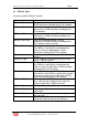
Kvaser LAPcan / LAPcan II Hardware Guide 10 Document revision history Revision 1 2 Date 2003-12 2006-10-27 Changes Original revision Reviewed – added DRVcan Fi versions Kvaser AB, Mölndal, Sweden — www.kvaser.