M1500 / M1500T 15.0” XGA TFT NEMA 4/12 Flat Panel Monitor User’s Guide User’s Guide Document No. DOC-IWS-712C, Rel.
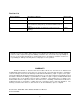
Revision List Revision Number Description of Change Release Date A Initial Release 9-2006 B Added Windows Vista driver to list of supported drivers, Added notes to driver list, Changed Logo, Corrected H X W Reversals on page 5 4-2007 C Added DVI functionality, UL Hazardous Locations Notes and Warnings 6-2008 Nematron reserves the right to make changes in specifications described herein at any time without notice in order to improve design and reliability.
Table of Contents WARRANTY .............................................................................................................................................. 2 Table of Contents ...................................................................................................................................... 3 Chapter 1 - Introduction ................................................................................................................................ 4 Features.....................
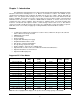
Chapter 1 - Introduction The M1500 is a high performance 15” color TFT flat panel monitor specifically designed for harsh industrial environments including Class I & II, Division 2 Hazardous Locations. The M1500 accepts standard analog VGA input and can display all VESA video modes up to 1280 x 1024 at 75Hz with 16 million colors. An optional 5-wire analog touch screen is available that offers both RS-232 and USB interface capability.
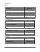
Specifications DISPLAY 11.97” x 8.98” Display Size (Active Area H x V) Native Resolution XGA, 1024 x 768 VESA Modes Supported Up to 1280 x 1024 @75Hz Displayable Colors 16M Brightness, Typical 250 Nit Contrast Ratio, Typical 550:1 Horizon/Vertical View Angle, CR>5, Typical 160/140 Backlight Life 40,000 hrs, Minimum Display Input Signal Analog 15-Pin D-Sub TOUCH SCREEN (Optional) Touch Screen Technology 5- Wire Analog Resistive Interface USB 1.
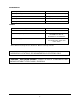
ENVIROMENTAL Operating Temperature 0C to 50C Operating Humidity 20% to 80% RH, noncondensing Operating Shock 15g peak acceleration, 11msec 0.006” peak to peak, 1g max Operating Vibration 5-2000 Hz Sea level – 10,000 feet Operating Altitude AGENCY Front Panel NEMA Rating NEMA 4/4X/12, IP65 FCC 47 CFR, Part 15, Class A EU CE Marking Compliance CE, EN 55022: Class A, EN 61000-3-2: Class A, EN 61000-3-3, EN 61000-6-2, Safety Agency Approvals UL 508 Listed, UL 1604 Listed*, cUL Listed CSA C22.
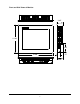
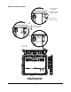
Front and Side Views of Monitor 2.65" 12.80" 3.95" 1.17" 15.80" 2.
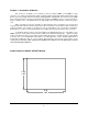
Chapter 2 - Installation of Monitor This monitor is intended to be mounted in and used where NEMA 4 and NEMA 12 type enclosures are employed. Enclosures made of heavier gauge metal work better because they won’t deform or bend as easily when the monitor’s sealing gasket is compressed. The monitor meets NEMA 4/12 sealing specifications when properly installed in an approved NEMA enclosure constructed from 14gauge or heavier steel.
Mounting Clip Installation .25" THICK MONITOR FRONT BEZEL COMPRESSABLE NEMA SEALING GASKET MOUNTING CLIP WITH 10x32 SCREW .
Connecting Power The M1500 monitor is powered from 100-240 VAC, 50/60 Hz or optionally from 24 VDC. Damage will occur if 100-240 VAC power is connected to an M1500 equipped with the 24 VDC input power option. M1500’s equipped with the 24 VDC option will have a “-24” suffix in their model number such as M1500-24 or M1500T-24.
WARNING – EXPLOSION HAZARD – DO NOT DISCONNECT EQUIPMENT WHILE THE CIRCUIT IS LIVE OR UNLESS THE AREA IS KNOW TO BE FREE OF IGNITABLE CONCENTRATIONS. Connection of VGA and Touch Screen Cables Connect either a 15-pin VGA or DVI-D cable and either an RS-232 or USB cable if the monitor is equipped with a touch screen. All communication cables should include a chassis ground shield. Hazardous location, Division 2, requires that all cables have adequate strain relief.
Turning on the Computer and Monitor With power applied to the monitor and all cables connected you may power up the computer and press the POWER button on the rear of the monitor. The POWER LED will switch from off to green. The monitor will perform an automatic self configuration and begin displaying an image. If no image appears, it may be because the monitor has the wrong video input selected. Press the UP button on the rear of the monitor to change between VGA and DVI-D inputs.
Chapter 3. - Monitor OSD and Settings On Screen Display (OSD) Controls The OSD controls are used for making adjustments to the monitor’s settings and are located on the back of the monitor. They consist of a single LED and five push buttons whose functions are described in the tables below.
Button and LED Functions BUTTON FUNCTION POWER Pressing this button once wakes the monitor up. Pressing the POWER button again turns off the back light inverter and puts the monitor in a reduced power state but the touch screen remains active. It is important to note that this switch does not disconnect power from the monitor.
OSD Menus and Settings MAIN MENU The following section describes the monitor’s OSD menus and settings. With the monitor powered up and receiving a normal video signal, pressing the MENU button once will cause the following screen to appear: Pressing MENU again will turn this screen off. Alternatively it will turn off after a time out period that is set in the SET UP sub-menu.
Pressing the SELECT button will cause the following screen to be displayed: Pressing the UP and DOWN buttons will adjust the brightness accordingly. Pressing the SELECT button again will deselect this function causing the following screen to appear: CONTRAST Pressing the DOWN button once and the SELECT button once will cause the following screen to appear: Pressing the UP and DOWN buttons will adjust the contrast accordingly. Pressing the SELECT button again will deselect this function.
COLOR With COLOR highlighted on the MAIN MENU pressing SELECT will cause the following screen to be displayed: PRESET1 and PRESET2 are preset color balances. PRESET1 is produces a bluer screen while PRESET2 produces a more aqua screen. Use the UP and Down buttons to highlight PRESET1 or PRESET2 and press SELECT to make your selection and return to the MAIN MENU.
POSITION With POSITION highlighted on the MAIN MENU, pressing SELECT will cause the following screen to be displayed: AUTO ADJUST AUTO ADJUST Highlighting AUTO ADJUST and pressing SELECT will initiate an automatic configuration and cause the “Processing Auto Configuration” message to be displayed. During the auto configuration process, the monitor automatically centers the screen horizontally and vertically, sets the clock and optimizes the phase.
HORIZONTAL With HORIZONTAL highlighted on the POSITION menu, pressing SELECT will cause the following screen to be displayed: Pressing the UP button causes the screen to move to the right while pressing the DOWN button causes the screen to move to the left. A setting number in the range of 0 to 100 is displayed. Pressing SELECT again will deselect the HORIZONTAL menu option and the setting will be saved.
SETUP OSD POSITION With SETUP highlighted on the MAIN MENU pressing SELECT will cause the following screen to be displayed: OSD POSITION 3 OSD TIME 20 SEC LANGUAGE ENGLISH EXIT With OSD POSITION highlighted on the SETUP menu, pressing SELECT will cause the following screen to be displayed: OSD POSITION 3 OSD TIME 20 SEC LANGUAGE ENGLISH EXIT The default position of the OSD menu is 3 which is in the center of the screen.
Pressing SELECT again will deselect the OSD POSITION adjustment menu and the setting will be saved. OSD TIME With OSD TIME highlighted on the SETUP menu, pressing SELECT will cause the following screen to be displayed: OSD POSITION 3 OSD TIME 20 SEC LANGUAGE ENGLISH EXIT Pressing the UP and DOWN buttons will the allow adjustment of the OSD time out setting in the range from 5 to 60 seconds. Pressing SELECT again will deselect the OSD TIME menu and save the current setting.
INPUT SOURCE With INPUT POSITION highlighted on the SETUP menu, pressing SELECT will cause the following screen to be displayed: OSD POSITION 3 OSD TIME 20 SEC LANGUAGE ENGLISH INPUT SOURCE PC EXIT Pressing the UP and DOWN buttons switches between PC (the 15-pin analog VGA input connector) and DIGITAL (the DVI-D input connector) Pressing SELECT will deselect the INPUT SOURCE option menu and save the current selection.
OSD Message Displays OUT OF FREQUENCY The following OSD message will appear if the horizontal or vertical refresh rate of the incoming video signal is outside the range of the monitor. NO SIGNAL When the monitor is first turned on it performs a set of self diagnostics. If no incoming video signal is detected immediately following self diagnostics, the following message will appear. This message will remain indefinitely until a valid signal is detected. The LED remains green.
POWER SAVER MODE The following message appears when the monitor is on but in DPMS (Display Power Management Signaling) mode. This occurs after a valid incoming video signal is no longer preset or when the PC has signaled the monitor to enter the POWER SAVER MODE. The message is displayed for 5 seconds and then removed. The LED remains amber. The “DIGITAL” POWER SAVER MODE message indicates the monitor is setup to receive incoming video through the DVI-D input connector.
Appendix VGA Input Pin Assignment DVI-D Pin No. Name Description 1 TMDS DATA2- TMDS DATA2 Differential Negative Signal 2 TMDS DATA2+ TMDS DATA2 Differential Positive Signal 3 TMDS DATA2 Shield Shield for TMDS Channel #2 4 N.C. No Connection 5 N.C. No Connection 6 DDC Clock The Data Line for the DDC Interface 7 DDC Data The Clock Line for the DDC Interface 8 N.C.
Analog 15- Pin D-Sub Pin No. Name Description 1 Red Red Analog Data 2 Green Green Analog Data 3 Blue Blue Analog Data 4 GND Ground 5 GND Ground 6 GND Ground 7 GND Ground 8 GND Ground 9 N.C.
Touch Screen Pin Assignment Serial RS-232 Pin No. Name Description Baud Rate 9600 1 DCD Data Carrier Detect Data Size 8 Bits 2 RX Receive Data Stop Bits 1 Bit 3 TX Transmit Data Parity No Parity (Only) 4 DTR Data Terminal Ready Handshaking Hardware CTS/RTS 5 GND Ground 6 DSR Data Set Ready 7 RTS Request To Send 8 CTS Clear To Send 9 RI Ring Indicator Pin No.