LABORATORY MANUAL AND INSTRUCTIONS Version 1.3 Metallurgical & Materials Engineering Dr. M.L. Weaver W.S. Rollings September 6, 2000 This manual describes operation of the Philips PW-1710 X-ray generator using PC-APD, techniques for data collection and analysis, and for instrument shutdown. All users should refer to the proper manuals for detailed information. IMPORTANT! DO NOT STORE YOUR DATA ON THE C: OR D: DRIVE OF THE COMPUTER. THE HARD DRIVE WILL BE PURGED WEEKLY.
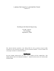
INSTRUCTIONS FOR PHILIPS X-RAY GENERATOR TURNING ON THE X-RAY GENERATOR 1) SIGN THE LOG SHEET! 2) Turn on the water chiller and wait 1 minute. The water pressure should be ≥ 40 psi. 3) On the x-ray generator, set the voltage and current to the lowest available setting (i.e., turn the kV and mA knobs all of the way to the left). 4) Turn on the x-ray generator by depressing the [ON] button on the display console (see Fig A).
10) On the small shutter control panel (Figure C), select window 2. Open the shutter by turning the selector knob to ∞ (one click to the right). Press the red ON button. The yellow light for shutter 2 will come on. 11) The instrument is now ready to collect data. Setup your data collection program in PC-APD and run it. SEE THE NOTES FOR PC-APD ON THE ACCOMPANYING PAGES. 12) Turn on the computer. In the Windows 3.1 environment, open the Philips folder and double click the “XMENU” icon.
25) Alter the field to collect a standard powder measurement. See Figure 3. 26) Press [Esc] twice to return to the main APD menu. 27) Choose DATA COLLECTION (D). 28) Choose IDENTIFY MEASUREMENT (I). 29) Enter the name of the identify program that was just created. Press [Enter]. Press F5 to see a list of available identify programs if necessary. 30) Enter the sample identification and a filename where the data will be stored in the appropriate fields.
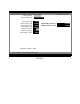
SYSTEM PARAMETERS 6-Sep-00 13:12:32 Licensee: Some Laboratory Tuscaloosa, AL Identification: Philips Analytical PC-APB, Diffraction software Data directory: C:\APD\DATA Temporary files: C:\APD\TMP Graphics Adapter: VGA Monitor: COLOUR Serial port 1: 2: 3: 4: Used for Graphics hard copy device: PRINTER Number of pens: Baudrate Databits Stopbits Parity Addr Check MOUSE DIFFRACTOMETER 4800 NOT PRESENT NOT PRESENT Esc=Last menu F5=Show names F10=Help FIGURE D. Schematic of SYSTEM PARAMETERS menu.
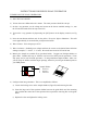
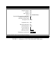
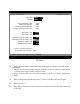
PARAMETERS FOR PW3710 BASED DIFFRACTOMETER Sample Changer: Spinner: Tube Anode: Focus: Programmable generator (PW1825): Generator tension [kV]: Generator current [mA]: Divergence slit: 6-Sep-00 13:12:32 NO NO Cu NF (Normal Focus) NO 45 40 1/12° Separate θ drive: NO Receiving Slit [mm]: Monochromator: Lower level [%]: Upper level [%]: Maximum 2θ [°]: 0.2 YES 30 80 120.000 Temperature control unit: NONE Esc=Last menu F1=Save current settings F10=Help FIGURE 2. Schematic of SYSTEM PARAMETERS menu.
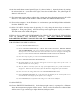
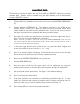
IDENTIFY: SCAN PARAMETERS New program: Type of Program: CONTINUOUS Step size [°2θ]: 0.020 Start Angle [°2θ]: 10.000 End Angle [°2θ]: 70.000 Scan time [h:m:s]: 0:50:00 Number of steps: 3000 Time per step [s]: 1.000 Scan speed [°2θ/s]: 0.020 6-Sep-00 13:12:32 Maximum d-value [Å]: Minimum d-value [Å]: Automatic analysis NO Esc=Last menu F9=Print Program F10=Help FIGURE 3 8.83820 1.
ANALYZING DATA The following procedures explain the use of the APD and IDENTIFY software to analyze collected data. Patterns must be treated using the APD software prior to identification using the IDENTIFY sofware. 1. Choose APD from X-MENU and from the main menu select PATTERN TREATMENT (P). 2. Choose ALPHA 2 STRIPPING (A). The patterns contained in the ICDD do not contain alpha 2 peaks, so in order to achieve the most accurate match these peaks should be removed from the collected data.
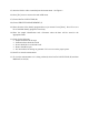
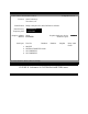
PEAK SEARCH 6-Sep-00 13:12:32 Input file: HDPE DI file: HDPE Create background file: Create peak data file: Creeate smoothed data file: Create second derivative file: NO NO NO NO Start angle [°2θ]: End angle [°2θ]: 0.200 0.260 Minimum peak tip width [°2θ]: Maximum peak tip width [°2θ]: Peak base width [°2θ]: Minimum significance: 0.04 1.00 2.00 0.75 .RD .DI Converty fixed slit intensities to automatic slit intensities: NO Esc=Menu F1=Start F5=Show Names F10=Help FIGURE 1 13.
17. Enter the name of the DI file (this file was created when the peak search was performed and has the same name as the raw data file but a DI extension) to be edited. 18. Press F1 to edit the lines. 19. Peaks can be added, deleted or moved. To add a peak press F4 for insert and then F8 for graphical mode. Then, position the cursor on the tip of the peak to be added and press F1 to accept the peak position. To delete a peak, use the F1 and F2 keys to page through the listing of peaks.
23. You will be brought to the PC-Identify main window (Figure 3). Figure 3. PC-Identify main window. 24. Choose IDENTIFY (I) and press F1 or ENTER. highlighted entry box as indicated in Figure 4.
Figure 4 25. Select the appropriate data directory and press ENTER. 26. Enter the name of the desired DI file or press F5 to select from a list of available DI files. 27. Press F1 to continue with analysis.
Figure 5 28. Use the ‘+’ or ‘-‘ keys to toggle the parameters setting to ‘Normal’, ‘Precise’ or ‘User defined’ depending upon the type of analysis that you want to do. A ‘Normal’ setting is appropriate for general analysis. The ‘User defined’ option can be used to limit the scope of your search to select ICDD cards or to compounds containing selected elements. Refer to the PC-IDENTIFY Users Manual for more details. 29. Press F1 to start the analysis. 30.
Figure 6 31. Press F8 to go to graphics mode. You will be prompted with a screen similar to Figure 7.
32. The list of patterns can now be compared to both the DI file and the raw data file. Pressing the ‘+’ and ‘-‘ keys steps through the list of candidates and pressing F4 and F3 insert and delete the reference patterns from the raw data field.
TURNING OFF THE X-RAY GENERATOR 1. Close the shutter by turning the appropriate knob on the Shutter Control Box (Figure C) to off. Lower the current to the lowest mA by turning the mA knob all of the way to the left. Reduce the voltage to 25 kV. WAIT 5 MINUTES. 2. Lower the voltage to 10 kV (i.e., lowest kV). 3. Turn off the X-ray generator by pressing the [STOP] button. Turn off the power by pressing the [OFF] button. 4. Feel the top of the x-ray tube, when it is cool the water chiller may be turned off.