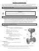
F-2200 Series Vortex Flow Meter Installation and Operation Guide For software version CF 4.7 and higher 12-15-08 1500 North Belcher Road • Clearwater, FL 33765 • Tel (727) 447-6140 • Fax (727) 442-5699 www.onicon.com • sales@onicon.
SAFETY INFORMATION This meter was calibrated at the factory before shipment. To ensure correct use of the meter, please read this manual thoroughly. Regarding This Manual: • • • • • • • • This manual should be passed on to the end user. Before use, read this manual thoroughly to comprehend its contents. The contents of this manual may be changed without prior notice. All rights reserved. No part of this manual may be reproduced in any form without ONICON’s written permission.
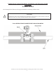
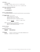
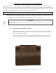
F-2200 Series Vortex Flow Meter Installation and Operation Guide Addendum December 12, 2008 The drawing below illustrates the proper method for insulating the flow meter. CAUTION ! Insulating the entire neck of the flow meter will increase heat transfer to the electronics enclosure and may in some cases cause premature failure of the electronics.
TABLE OF CONTENTS 1.0 INTRODUCTION .............................................................................................................. 7 1.1 Purpose of This Guide .............................................................................................. 7 1.2 Principal of Operation .............................................................................................. 7 1.3 Features and Specifications .....................................................................................
F-2200 Series Vortex Flow Meter Installation and Operation Guide • Revised 12/08 6
SECTION 1.0: INTRODUCTION We, at ONICON INCORPORATED, would like to thank you for purchasing our F-2200 Series Vortex Flow Meter. As our valued customer, our commitment to you is to provide fast reliable service and assistance, while continuing to offer you new products to meet your growing flow measurement needs. 1.
ACCURACY Volumetric flow ±1% of reading accuracy (±2% for ¾” & smaller sizes) Mass flow ±1.5% of reading accuracy (±2.
1.4 ADDITIONAL REQUIRED MATERIALS Installer is responsible for providing suitable flanges and fasteners to connect the meter to the process piping. In addition, most installations will also require one reducer, one expander, pipe supports and a sufficient length of straight pipe (pipe diameter = meter size) to meet the installation requirements outlined in this manual.
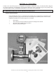
SECTION 2.0: UNPACKING F-2000 series vortex flow meters are shipped in one package. Additional items, if ordered, will be shipped in separate packaging. All shipments are insured for damage in transit. Carefully inspect each package and notify the freight carrier and ONICON immediately if any items arrive damaged. 2.
SECTION 3.0: INSTALLATION INFORMATION The F-2000 series vortex flow meter must be installed by a technician qualified to work with pressurized liquid, steam and/or gas flow and must conform to all federal, state and local building codes. ONICON will be happy to assist with technical recommendations and to provide guidance via telephone or mail. On-site engineering, installation and service are also available, at additional cost. 3.
The diagrams shown below illustrate the correct meter orientation for vertical and horizontal pipe. 3.1.2 Maximum Allowable Difference Between Inside Diameter Of Meter Body And The Connecting Pipe The table below provides the maximum allowable difference between the diameter of the flow meter body and the connecting pipe. Nominal Meter Size (in.) 1” 1 1/2” 2” 3” 4” 6” 8” Meter Body Diameter (in.) 1.05 1.61 2.07 3.07 4.03 6.07 7.98 Maximum Pipe ID Difference (in.) 0.016 0.016 0.024 0.024 0.024 0.031 0.
3.1.3 Straight, Unimpeded Inlet And Outlet Runs D = Meter Size (Nominal diameter in inches) With a flow straightener, the inlet pipe length may be reduced by 50%. For example, with a control valve upstream, the inlet length is 25D instead of 50D. The minimum inlet pipe length including the flow straightener must always be at least 12D. 3.1.4 Minimizing Pipe Vibration Pipe vibration caused, for example, by the action of pumps, valves, etc.
3.1.5 Locating The Meter In A Pipline That Runs Parallel To A Wall Wherever possible, the distance between the pipe centerline and the wall should be greater than 20”. This will allow for access to the electronics enclosure compartment where wire terminations are made. If adequate space is not available, first connect all the cables to the terminals in the connection compartment (power supply and outputs) and then run the wires to an intermediate junction box (also see Section 3.
3.2 MECHANICAL INSTALLATION 3.2.1 Orient The Display For Convenient Viewing Both the electronics enclosure and the display itself can be rotated to four different orientations to change the viewing angle for the display. If necessary, this should be done before the meter is installed. 3.2.1.1 Rotating the electronics enclosure The electronics enclosure is attached to the meter body with (4) 5mm Allen head screws.
3.2.1.2 Rotating the display To rotate the display, first unscrew the cover using the special tool provided for this purpose. Once the cover is removed, the (4) Philips head screws that secure the display are exposed. To rotate the display, remove these screws and carefully move it to the desired position making certain that the interconnecting cable is not damaged in the process.
3.3.2 Temperature Measurements ONICON F-2000 series vortex meters are supplied with an internal PT 1000 type RTD temperature sensor located within the shedder bar. This sensor provides an accurate temperature measurement at the point where the flow rate is being measured. Flow meters supplied with this option will display the medium temperature and deliver an output signal that is temperature compensated for mass and/or normalized flow. 3.
SECTION 4.0: START UP AND TROUBLESHOOTING 4.1 START UP When the power is applied to the F-2000 series vortex meter, alphanumeric characters will appear on the display. Initially, the meter will operate in a “TEST” mode where self diagnostic checks are performed on the pre-amplifier and sensor circuits. Following this, configuration data is loaded from the non-volatile memory and the program advances to the measurement mode.
4.3 OPERATING THE DISPLAY Please read the entire procedure before proceeding. Wiring diagrams are located in the Appendix. A worksheet for checking off the following steps and recording measured values is located on the next page. key Hall Effect Switch key Hall Effect Switch key Hall Effect Switch Display page scroll (measurement mode) i IMPORTANT NOTE Do not attempt to enter the program mode without first contacting ONICON service.
4.4 ERROR HANDLING The meter can detect errors in either the test or the measurement modes. When in the measurement mode, a blinking vertical bar will appear in the top left corner of the display indicating an error has been detected. If the error reporting function is enabled, error messages will be displayed as separate menu pages. The first line of the error menu page indicates the total number of errors and the second line displays the error message. Measurement mode error messages are listed below.
4.5 TROUBLESHOOTING HINTS REPORTED PROBLEM A non-zero flow indicated when no actual flow is in the pipe. POSSIBLE SOLUTIONS • Mains interference due to improper Earth ground connection. The protective Earth PE terminal should be properly grounded (see page 17). • Excessive mechanical vibration in the pipe. If so, support the pipeline near the meter perpendicular to both the axis of the pipe and the axis of the shedder bar. • This problem may also be solved by reducing the factory set gain.
SECTION 5.0: FLOW STRAIGHTENER FOR VORTEX FLOW METERS DESCRIPTION The optional flow straightener accessory for ONICON F-2000 Series Vortex Flow Meters is a wafer-style flow conditioner that is designed to be installed between two recessed flanges (provided by installer) that are located a specified distance upstream of the flow meter. Use of a flow straightener significantly reduces the upstream straight pipe length requirement for ONICON Vortex Flow Meters.
ONICON F-2000 SERIES STEAM METER, NOTE 1 300# ANSI FLANGE (600# ANSI FLANGE OPTNL) ECCENTRIC REDUCER, NOTE 2 FLOW STRAIGHTENER, NOTE 3 UPSTREAM OBSTRUCTION SEE TABLE 1 2 DIAMETERS DIMENSION B MINIMUM UPSTREAM PIPE RUN 5 DIAMETERS MINIMUM DOWNSTREAM PIPE RUN DIMENSION A REQUIRED DIMENSIONS FOR INSTALLATIONS WITH FLOW STRAIGHTENER DIMENSION A DIMENSION B UPSTREAM TOTAL UPSTREAM DISTANCE BETWEEN OBSTRUCTION PIPE RUN FLOW METER AND STRAIGHTENER SINGLE 90 12 DIA 10 DIA TEE 12 DIA 10 DIA RDCR/EXPNDR 12 DI