
PSW-H Installation and User Manual

www.phocos.com 18 | P a g e
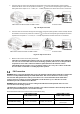
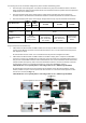
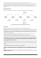
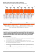
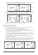
Example: 4 Units on Phase 1, 4 Units on Phase 2 (split-phase)
Note: this example excludes circuit breakers, SPDs, RCDs and bus bars for better visibility.
Fig. 18: Power connections of 4 units on P1, 4 units on P2
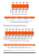
Fig. 19: Communication connections of 4 units on P1, 4 units on P2
Commissioning
CAUTION: Before continuing, ensure the wiring is correct according to the previous chapter. Particularly that
all units are connected to the same neutral wire at the AC input and all AC output neutral terminals are
connected to a separated common neutral wire. Ensure that all AC input breakers and AC output breakers are
open on each individual Any-Grid unit and that each unit is turned off with its AC output on/off switch. Ensure
each unit is disconnected from PV but connected to the battery via its battery breaker / fuse. The battery
breaker must be closed / inserted to ensure each unit can function for commissioning.
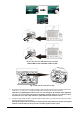
Parallel in Single Phase
Follow these steps once the wiring is completed:
1. Turn on one unit with its AC output on/off switch. If PV is available, switch it on with its breaker. Otherwise, if
an AC source is available, switch it on with its AC input breaker.
2. In the Settings Menu (see chapter “Device Operation Settings”) navigate to settings menu 28.
3. Turn the AC output on/off switch off to deactivate the AC output. The unit will remain in Stand-By mode for
under a minute and the display will stay on for this time.
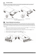
4. Set the menu number 28 setting from the default value “Single” (SIG) to “Parallel” (PAL). This will not be
possible if the unit is not turned off as described in the previous step. Press so the entry stops blinking.
Now press the button to accept the new setting and return to the main view.
5. Switch off the PV and AC input breaker if they were on. Wait for the unit to shut down automatically, the
display will then turn off completely.
6. Repeat steps 1 to 5 with each further unit connected in parallel.