
PSW-H Installation and User Manual


www.phocos.com 10 | P a g e
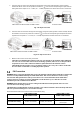
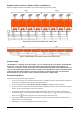
3. Insert the three AC source wires through the rectangular casing hole (cable gland for 120 Vac models)
marked “AC INPUT”. Insert the “PE” protective conductor first into the corresponding AC input terminal
and tighten with a torque of 1.4 ~ 1.6 Nm (1.0 ~ 1.2 lbf⋅ft). Repeat for the neutral “N” and live “L” conductors.
PSW-H-5KW-120/48V and PSW-H-6.5KW-120/48V All other models
Fig. 7: AC input connection
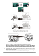
4. Insert the three AC load wires through the rectangular casing hole (cable gland for 120 Vac models) marked
“AC OUTPUT”. Insert the “PE” protective conductor first into the corresponding AC output terminal and
tighten with a torque of 1.4 ~ 1.6 Nm (1.0 ~ 1.2 lbf⋅ft). Repeat for the neutral “N” and live “L” conductors.
PSW-H-5KW-120/48V and PSW-H-6.5KW-120/48V All other models
Fig. 8: AC Output connection
5. Make sure the six wires are securely connected.
CAUTION: Over-tightening the terminal screws can cause damage to the terminal, under-tightening
can cause a loose connection and excessive heat during operation, make sure to use the prescribed
torque. Ensure none of the conductor insulation is jammed between the terminal contacts.
CAUTION: Ensure the polarity is correct on all wires. Failure to do so may cause a short-circuit at the
AC source when several units are working in parallel operation.
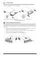
PV Connection
WARNING: Before connecting the PV module array to the PV input of the Any-Grid, install a DC circuit breaker
between each Any-Grid PV terminal pair and the PV modules. This ensures the inverter can be securely
disconnected during maintenance and is protected from over-current of the PV modules. PV modules
produce a dangerous voltage even at low light. Make sure the breaker is open / off for the rest of the
installation procedure until instructed otherwise.
WARNING: Ensure the PV cables are sized according to the table below. Inadequate PV cables can cause
excessive heat or fire during operation.
CAUTION: Short-circuiting the PV+ to the PV- terminal or any of these terminals to the metal body of the unit
will cause permanent damage not covered under warranty.
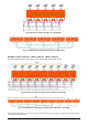
Recommended PV cable cross-section and DC circuit breaker rating:
Any-Grid model
PSW-H-5KW-230/48V
PSW-H-3KW-230/24V
PSW-H-3KW-120/24V
PSW-H-5KW-120/48V
PSW-H-6.5KW-120/48V
PV cable cross-section
2.5 ~ 16 mm², AWG 5 ~ AWG 13
4 ~ 6 mm², AWG 10 ~ AWG 12
Circuit breaker rating
30 Adc, min. 450 Vdc
30 Adc, min. 250 Vdc
25 Adc, min. 250 Vdc
per PV input