
PSW-H Installation and User Manual


www.phocos.com 11 | P a g e
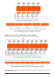
For selecting the correct PV module configuration, please consider the following points:
• The total open circuit voltage (Uoc / Voc) of the PV module array may never exceed the values in the table
below. Consider the coldest possible temperatures at the installation location together with the temperature
coefficient of the PV modules used.
• The total maximum power point voltage (Umpp / Vmpp) of the PV module array must be above the
minimum values in the table below. Consider the hottest PV module temperatures at installation location.
• The total maximum power point current (Impp / Ampp) of the PV array may not exceed the values below.
Any-Grid model
PSW-H-
5KW-
230/48V
PSW-H-
3KW-
230/24V
PSW-H-5KW-
120/48V
PSW-H-6.5KW-
120/48V
PSW-H-3KW-
120/24V
Max. PV voltage (Uoc)
450 Vdc
250 Vdc
Min. PV mpp voltage
(Umpp)
120 Vdc
90 Vdc
Max. mpp current
(Impp)
27.5 Adc
(up to 22 Adc
actually usable)
22.5 Adc (up to 18
Adc usable) per
input, 30 Adc total
max. usable
22.5 Adc (up to 18
Adc usable) per
input, 36 Adc total
max. usable
27.5 Adc (up to
22 Adc actually
usable)
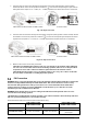
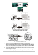
Steps to connect the PV module array:
1. PSW-H-5KW-120/48V and PSW-H-6.5KW-120/48V: if the PV array has MC4 connectors, do not remove them.
If the array has different connectors, cut them off and remove 8 mm / 0.3 in of insulation from the positive
and negative PV cables.
All other models: remove 10 mm / 0.4 in of insulation from the positive and negative PV cables.
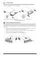
2. PSW-H-5KW-120/48V and PSW-H-6.5KW-120/48V: use an MC4 crimping tool to crimp the included MC4
connectors to the PV array (see Fig. 9.1, top) if the array does not already have compatible MC4 connectors.
Only use the included MC4 connectors if the PV cable has the cross-section outlined in the first table of this
chapter
. Double-check polarity. Then insert the finished MC4 connectors into the PV1 and PV2 connectors
on the inverter, positive (+) on the left and negative (-) on the right (see Fig. 9.1, bottom).
CAUTION: Ensure correct polarity before connecting. Failure to do so will damage the PSW-H.
All other models: insert the two PV wires through the rectangular casing hole (cable glands for 120 Vac
models) marked “PV input”. Insert the positive PV cable into the “PV+” terminal and the negative PV cable
into the “PV-“ terminal (see Fig. 9.2).
CAUTION: Ensure correct polarity before connecting. Failure to do so will damage the PSW-H.
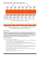
Insert stripped PV+ wire into female MC4 pin and crimp:
Insert assembled pin into corresponding connector housing:
Insert stripped PV- wire into male MC4 pin and crimp: