
PSW-H Installation and User Manual


www.phocos.com 12 | P a g e
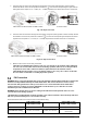
Insert assembled pin into corresponding connector housing:
Tighten both connector domes with a spanner:
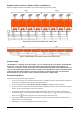
Fig. 9.1: PV connection, PV2 input shown as example
(PSW-H-5KW-120/48V and PSW-H-6.5KW-120/48V)
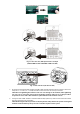
Fig. 9.2: PV connection (all other models)
3. All models except PSW-H-5KW-120/48V and PSW-H-5KW-120/48V: Tighten both PV terminal screws with a
torque of 1.4 ~ 1.6 Nm (1.0 ~ 1.2 lbf⋅ft) and make sure the two wires are securely connected.
CAUTION: Over-tightening the terminal screws can cause damage to the terminal, under-tightening
can cause a loose connection and excessive heat during operation, make sure to use the prescribed
torque. Ensure none of the cable insulation is jammed between the terminal contacts.
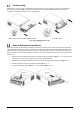
4. If using the PSW-H-5KW-120/48V or PSW-H-6.5KW-120/48V, repeat step 1 and 2 for the second PV terminal
pair and a second PV array, if available.
CAUTION: If using two PV arrays for this model, they must be independent. The positive and negative
terminals of the two PV arrays may not touch each other anywhere in the system.