
PSW-H Installation and User Manual


www.phocos.com 13 | P a g e
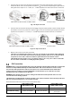
Final Assembly
After Battery, PV and AC wiring is completed, please slide the bottom cover back up on the unit, re-connect the 3
wire harnesses removed in Fig. 4, and secure it by fastening the five (PSW-H-5KW-120/48V and PSW-H-6.5KW-
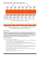
120/48V) or two (all other models) screws as shown below.
PSW-H-5KW-120/48V and PSW-H-6.5KW-120/48V All other models
Fig. 10: Re-applying bottom cover
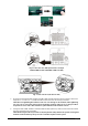
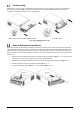
Remote Display Panel Installation
The display module can optionally be removed and installed in a remote location with an optional communication
cable. Please take the following steps to implement this remote panel installation. Use a standard straight Ethernet
patch cable (Cat5 or higher) with male RJ45 connectors on both sides (not included). A maximum cable length of 20
meters or 66 feet is recommended. Follow the steps below to remove the display module and install it away from the
inverter unit.
1. Remove the screw holding the bracket on the bottom of the display module (Fig. 11 → ①) and push down
the display unit from the case slightly while removing the metal bracket.
2. Keep pushing the display module down, taking care not to damage the connected cable (Fig. 11 → ②).
3. Remove the cable connected to the display module (Fig. 11 → ③).
4. Screw the bracket removed in Fig. 11 → ① back in place (Fig. 11 → ④).
Remove
Push