
PSW-H Installation and User Manual


www.phocos.com 14 | P a g e
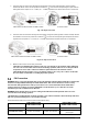
Fig. 11: Remote display removal
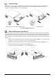
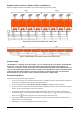
5. Drill the three mounting holes in the marked distances of 70 mm, 2.76 in into each other (Fig. 12, left). Use
M3, size no. 4 diameter screws. The screw heads must be between 5 ~ 7 mm, 0.2 ~ 0.3 in. Screw the bottom
two screws into the wall where the display module is to be mounted and let the screw heads protrude 2
mm, 0.08 in. from the wall. Slide the display down on the protruding screw heads. Now insert and tighten
the third screw at the top (Fig. 12, right).
Fig. 12: Remote display mounting hole locations
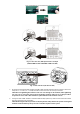
6. Install one end of the Ethernet patch cable (not included) into socket (Fig. 2, top right) on the display
module (right side). Install the other end of the Ethernet patch cable into socket (Fig. 2, bottom left) on
the Any-Grid unit.
7. If using Lithium batteries designed for battery management system (BMS) communication such as
Pylontech batteries, please visit www.phocos.com for a current list of batteries supported with BMS
communication. Connect the special battery BMS cable (ask your dealer for details) to socket (Fig. 2).
CAUTION: Ensure the battery and BMS is compatible with the Any-Grid and that the pin location is
correct before connection. Damage to any communication port or the battery due to incorrect
connection or cables is not covered by warranty. Do not use any inverter communication cables
included with your battery, consult your Phocos dealer for appropriate Any-Grid cables instead.
Pin (see Fig. 2)
1
2
3
4
5
6
7
8
Function
RS-232 RX
RS-232 TX
RS-485 B
+12 Vdc
RS-485 A
CAN H
CAN L
GND
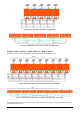
Installing Multiple Units in Parallel, Split Phase or 3-Phase
Configuration
Introduction
This entire chapter is only relevant if using more than one Any-Grid unit. Multiple Any-Grid units of the same
model number can be used either in parallel on a single phase, split-phase / 2-phase (only 120 Vac models), or in a 3-
phase configuration with a common neutral. All units must be connected to the same battery bank. This chapter is an
addition to all other sections above in the chapter “Installation”, please adhere to all guidelines and safety
instructions in those sections accordingly.
Parallel operation on a single phase is possible with up to 9 units.
Alternatively, 3-phase configuration is possible, whereby at least one unit must be installed on each of the 3 phases
Pull
Screw in