
PSW-H Installation and User Manual


www.phocos.com 15 | P a g e
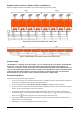
with a maximum of 7 units on a phase. The total number of units may not exceed 9 in any case.
For 120 Vac models split-phase (2-phase) operation is possible whereby at least one unit must be installed on each of
the 2 phases with a maximum of 8 units on a phase. The total number of units may not exceed 9 in any case.
CAUTION: If using an AC source, each unit must be connected to a neutral and a phase conductor, never two
phases.
Mounting the Units
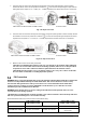
When installing multiple units, please keep a minimum distance between the units as shown in Fig. 13.
Fig. 13: Minimum distance between units and to other objects
Connections
Use the cable cross-sections, tightening torque and connectors as described for a single unit.
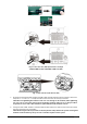
Battery Connection: Make sure to use a separate DC fuse or circuit breaker for each unit. Instead of connecting each
unit to the battery, connect each positive battery cable to a bus bar, and each negative battery cable to a second bus
bar. These bus bars are then connected to the battery terminals. The cross-section of the bus bars, and the cables
from the bus bars to the battery terminals should equal the recommended battery cable cross-section per unit, times
the number of units connected to it.
The minimum recommended battery capacity for lead-based batteries is 200 Ah per connected Any-Grid. For
example, in a system with 3 units, the battery bank should have a capacity of at least 600 Ah.
CAUTION: All inverters must share the same battery bank. Otherwise, the inverters will go into fault mode.
CAUTION: Please install at least a breaker at the battery terminals and AC input of every individual Any-Grid
unit. This will ensure each unit can be securely disconnected during maintenance and fully protected from
over-current of battery or AC input. Use the breaker ratings as described in the chapters “Battery Connection”
and “AC Input and AC Output Connection”.
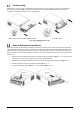
AC Connections: Regarding AC input and output, please also follow the same principle. Use the wiring cross-section
and circuit breaker as defined for each individual unit, then attach those wires to bus bars. The bus bars from the AC
input are then connected to the AC source, the bus bars from the AC output are connected to the distribution panel
and loads.
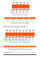
PV Connections: Use the PV connection as described for individual units. Each unit must be connected to its own PV
array and must not have any electrical contact to any other units’ PV arrays.
CAUTION: Connecting a single PV array to multiple Any-Grids simultaneously will damage the Any-Grid units.
If using PV, each unit must be connected to its own individual PV array, not electrically shared with any other
units.
WARNING: Ensure all circuit breakers are open / disabled before wiring the units so that there is no voltage on
all battery, AC and PV wires.