
PSW-H Installation and User Manual


www.phocos.com 17 | P a g e
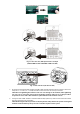
Fig. 14: Power connections of 5 units on a single phase
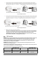
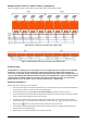
Fig. 15: Communication connections of 5 units on a single phase
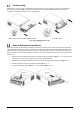
Example: 7 Units on Phase 1, 1 Unit on Phase 2, 1 Unit on Phase 3
Note: this example excludes circuit breakers, SPDs, RCDs and bus bars for better visibility.
Fig. 16: Power connections of 7 units on P1, 1 unit on P2, 1 unit on P3
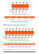
Fig. 17: Communication connections of 7 units on P1, 1 unit on P2, 1 unit on P3
Notice that because there is only one unit on phase 2 (P2) and phase 3 (P3), there are no green current sharing cables
connected to these two units.