
PSW-H Installation and User Manual


www.phocos.com 22 | P a g e
8.0 Operation
Inverter Power ON/OFF
Fig. 20: Display module ON/OFF load button location
Ensure the “ON/OFF” switch located on the display module (Fig. 20) is in the “OFF” position after the initial installation
(the button must not be depressed).
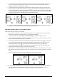
Now activate the circuit breakers or insert the fuses to energize the various inputs and outputs in the following order
(skip any that are not connected):
1. Battery
2. AC input
3. PV input
4. AC output
Next, press the “ON/OFF” switch to turn on the AC output and thus connected AC loads and the entire unit.
If the “ON/OFF” switch is in the “OFF” position, then the unit will be completely off when there is insufficient sunlight.
If PV modules are connected and there is sufficient PV voltage, the unit and display will wake up automatically to
charge the batteries during the day. Once the PV voltage drops below the threshold, the unit will again turn
completely off to save energy during the night. The AC output and thus the AC loads will remain off as long as the
“ON/OFF” switch is in the “OFF” position.
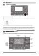
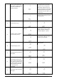
Display and Control Module
The display and control module, shown in Fig. 21, includes six LED indicators, six function buttons, an ON/OFF
button and a LCD screen, indicating the operating status and allowing the programming of settings parameters.
Fig. 21: Display module buttons and indicators
LCD screen
Source
LED 2
Source
LED 1
Source
LED 3
Inverter ON/OFF
button
Function
buttons
Status
indicators