
PSW-H Installation and User Manual


www.phocos.com 30 | P a g e
26
Boost battery charging
voltage
57.6 Vdc (48 Vdc model Default)
28.8 Vdc (24 Vdc model Default)
If “User-defined” is selected in
settings menu 05, this value can be
changed.
Available values: 48.0 ~ 64.0 Vdc in
0.1 Vdc increments for 48 Vdc
model.
Available values: 24.0 ~ 32.0 Vdc in
0.1 Vdc increments for 24 Vdc
model.
27
Floating battery charging
voltage
55.2 Vdc (48 Vdc model Default)
27.6 Vdc (24 Vdc model Default)
If “User-defined” is selected in
settings menu 05, this value can be
changed.
Available values: 48.0 ~ 64.0 Vdc in
0.1 Vdc increments for 48 Vdc
model.
Available values: 24.0 ~ 32.0 Vdc in
0.1 Vdc increments for 24 Vdc
model.
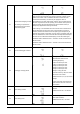
28
AC output mode
Note: To avoid damage, this
value can only be changed if
the inverter is in Stand-By
mode (AC output turned off).
See chapter “Installing
Multiple Units in Parallel,
Split Phase or 3-Phase
Configuration” for detailed
instructions.
Split-phase / 2-phase modes
are only available on 120 Vac
models.
Single: This unit is used alone in
a single-phase application
(Default)
Parallel: This unit is one of several
units in a single-phase application
Phase L1: This unit is one of
several units and on phase 1 in a
three-phase application
Phase L2: This unit is one of several
units and on phase 2 in a three-
phase application
Phase L3: This unit is one of
several units and on phase 3 in a
three-phase application
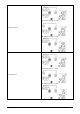
Phase L1: This unit is one of several
units and on phase 1 in a split-
phase (2-phase) application
Phase L2: This unit is one of
several units and on phase 2 in a
split-phase (2-phase)
application, with 120° phase-
shift relative to phase 1:
Phase L2: This unit is one of several
units and on phase 2 in a split-
phase (2-phase) application, with
180° phase-shift relative to phase 1: