
PSW-H Installation and User Manual


www.phocos.com 5 | P a g e
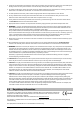
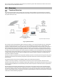
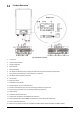
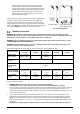
Product Overview
Fig. 2: Product Overview
1. LCD screen
2. Inverter status indicator
3. Charging indicator
4. Fault indicator
5. Function buttons
6. AC output on/off switch (solar charging still functions when the AC output is powered off)
7. AC input terminals (public grid or AC generator connection)
8. AC output terminals (load connection)
9. PV terminals
10. Battery terminals
11. Resettable circuit breaker
12. Remote display unit communication port
13. Parallel communication port (for inter-connecting multiple Any-Grid units)
14. Current sharing port (for inter-connecting multiple Any-Grid units)
15. Relay contact
16. USB-OTG communication port
17. Output source indicators and USB function indicators
18. Battery Management System (BMS) communication port: CAN, RS-485 and RS-232
19. RS-232 communication port
20. Battery wiring extension box (only included with PSW-H-3KW-120/24V and PSW-H-6.5KW-120/48V)
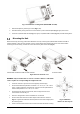
Display Unit
Pin 1 Pin 8
PSW-H-5KW-120/48V and PSW-H-6.5KW-120/48V
All other models