
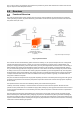
PSW-H Installation and User Manual


www.phocos.com 7 | P a g e
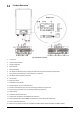
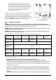
Fig. 3.2: Installation of cable glands (PSW-H-5KW-120/48V)
1. Remove faceplate by removing 4 screws (Fig. 3, left).
2. Assemble battery wiring extension box and mount in place of the faceplate (Fig. 3, right) with screws.
3. Install the 5 (PSW-H-3KW-120/24V, Fig. 3.1, right) or 4 (PSW-H-5KW-120/48V, Fig. 3.2) included cable glands.
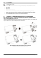
Mounting the Unit
Before connecting all wirings, please take off bottom cover by removing five (PSW-H-5KW-120/48V and PSW-H-
6.5KW-120/48V) or two (all other models) screws as shown below and carefully sliding the cover down. Before
removing the cover entirely, remove the 3 wire harnesses by their connectors (Fig. 4).
PSW-H-5KW-120/48V and PSW-H-6.5KW-120/48V All other models
Fig. 4: Removal of bottom cover
WARNING: Only mount this unit on concrete or another solid non-combustible
surface capable of securely holding the weight of the unit.
• Install this inverter at eye level to ensure legibility of the display
• Ensure the ambient temperature is between -10 ~ 50 °C, 14 ~ 122 °F at all
times. In order to fulfill UL requirements, inverters must be operated at an
ambient temperature of -10 ~ 40 °C, 14 ~ 104 °F.
• Avoid excessively dusty environments, direct sunlight and corrosive
environments such as salty air.
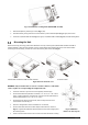
• The unit is designed for vertical installation on a solid wall
• Ensure a minimum distance to other objects and surfaces as shown in
Fig. 5.1 to guarantee sufficient heat dissipation and to have enough space
for removing wires.
• Install in a room where noise is not an issue as the unit has fans for cooling.
Fig. 5.1: Minimum
distance to other objects