
PSW-H Installation and User Manual


www.phocos.com 8 | P a g e
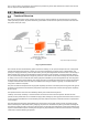
Under maximum load, the fan noise typically does not
exceed 60 dBa. Under no load, but with the AC output
turned on, the minimum noise is approximately 35 dBa, as
the fans rotate at about 30% of their maximum speed. The
fans are speed-controlled according to current PV and
inverter power. Air is taken in from the top vents and
expelled toward the bottom.
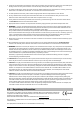
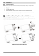
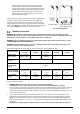
Install the unit by using four (PSW-H-5KW-120/48V and PSW-H-5KW-
120/48V) or three (all other models) M4 or M5 screws (Fig. 5.2)
appropriate for the weight of the unit and wall material, use wall
plugs. The bottom screw hole is only accessible after removal of the
bottom cover (Fig. 4). This bottom cover must remain removed for the
rest of this “Installation” chapter until instructed otherwise.
Battery Connection
WARNING: The installation of this unit may only be undertaken by qualified personnel with appropriate
training. High voltages in and around the battery and unit can cause serious injury or death. This unit must be
installed in accordance with rules and regulations at the site of installation.
WARNING: Choose a suitable battery fuse as outlined in the chapter “Important Safety Information”, section
“OVERCURRENT PROTECTION FOR BATTERY”.
WARNING: Ensure the battery cables are sized according to the table below. Inadequate battery cables can
cause excessive heat or fire during operation.
Recommended battery cable cross-section, battery size and fuse / DC circuit breaker rating:
Any-Grid model
PSW-H-5KW-
230/48V
PSW-H-5KW-
120/48V
PSW-H-6.5KW-
120/48V
PSW-H-3KW-
230/24V
PSW-H-3KW-
120/24V
Battery cable
cross-section
35 ~ 50 mm²
AWG 0 ~ AWG 2
50 mm², AWG 0
70 mm²
AWG 2/0
35 ~ 50 mm², AWG 0 ~ AWG 2
Nominal battery
voltage
48 Vdc
24 Vdc
Min. battery
capacity (lead-
based)
200 Ah
Battery discharge
current capability
140 Adc cont.
280 Adc surge
(5s)
115 Adc cont.
280 Adc surge
(5s)
154 Adc cont.
308 Adc surge
(5s)
168 Adc cont.
336 Adc surge
(5s)
145 Adc cont.
336 Adc surge
(5s)
Fuse / breaker
rating
175 Adc,
min. 66 Vdc
175 Adc,
min. 66 Vdc
200 Adc,
min. 66 Vdc
210 Adc, min.
33 Vdc
210 Adc, min. 33
Vdc
Steps to connect the battery:
1. WARNING: Ensure the battery cables are not yet connected to the battery.
CAUTION: Ensure none of the cable insulation is jammed in the ring terminal before crimping.
Crimp one battery ring terminal (included) to each the positive and negative battery lead (unit side). If choosing
ring terminals other than the included ones, make sure they have an inside ring diameter of 8.4 mm, 0.31 in
(PSW-H-5KW-120/48V and PSW-H-6.5KW-120/48V) or 6.4 mm, 0.25 in (all other models) to fit the battery terminal
bolts of the Any-Grid securely.
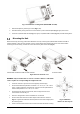
2. Remove the pre-installed nuts from the battery terminal bolts. Insert the ring terminal of the battery cables
through the casing holes (cable glands for 120 Vac models) and flat onto the corresponding battery terminal
(Fig. 6). Screw down the previously removed nuts with a torque of 5 Nm, 3.7 lbf-ft (PSW-H-5KW-120/48V and
PSW-H-6.5KW-120/48V) or 2 ~ 3 Nm, 1.5 ~ 2.2 lbf⋅ft (all other models). Ensure the ring terminals sit flush on the
connectors.
CAUTION: Do not apply any anti-oxidant substances to the battery terminals of the unit before they are
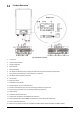
All other models PSW-H-5KW-120/48V
PSW-H-6.5KW-120/48V
Fig. 5.2: Mounting holes