
User manual


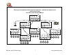

Panels Overview
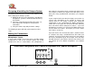
Front panel includes:
One/Off switch
Power LED indicator
¼” audio Monitor jack – this jack is used for setting and
testing the unit. During setup (with the setup wizard) the
microphone inputs and the system output will be assigned
to this jack (depending on the setting phase – see details
in the Setup Wizard chapter).
Optional Telephone interface – see details in the next
chapters
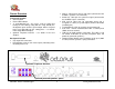
Back panel includes
Four input XLR connectors
LED indicator (next to each of the inputs) indicating when
Phantom power is on.
SPK In - RCA jack for the far-end signal (connected to the
CODEC’s speaker’s out connector).
Audio Out - RCA jack for system out signal (connected to
the CODEC’s input’s connector).
XLR jack for either Link Up connection (when unit is
assigned as a Slave) or system output (similar to the Audio
Out RCA jack).
Terminal Block (2 Pin) for speaker out (non-powered).
Com Port - RS232 communication with a control panel
(AMX, Crestron or other).
USB jack for USB computer connection. The USB is used
for control, audio data (in and out) and power (does not
power the “powered speakers”).
Optional Power Module panel including an AC jack (220V
or 110V) and four speaker’s spring connection.
Optional Telephone Interface
Optional powered speakers’ panel
Phoenix Audio Technologies www.phnxaudio.com
4