PHOENIX CONTACT GmbH & Co. KG Flachsmarktstraße 8, 32825 Blomberg, Germany Fax +49-(0)5235-341200, Phone +49-(0)5235-300 www.phoenixcontact.com MNR 9037067 / 2012-02-15 DE Hybrid-Motorstarter mit Wendefunktion EN Hybrid motor starter with reversing function FR Démarreur moteur hybride avec fonction d'inversion ES Controlador de arranque híbrido con función inversor RU Комбинированный пускатель электродвигателя с функцией поворота Art.-Nr.: 2297031 Art.-Nr.
DEUTSCH ENGLISH FRANÇAIS 2 Inhaltsverzeichnis Seite 1. Kurzbeschreibung.......................................................................................4 2. Sicherheitsbestimmungen / Errichtungshinweise .......................................5 3. Anschlusshinweise ..................................................................................... 6 4. Funktion .....................................................................................................7 5. Applikationsbeispiele ............
ESPAÑOL РУССКИЙ Indice Página 1. Descripción resumida ...............................................................................31 2. Prescripciones de seguridad / indicaciones de instalación ......................32 3. Indicaciones de conexión .........................................................................33 4. Función ....................................................................................................34 5. Ejemplos de aplicación - Descripción ...............................
DEUTSCH Hybrid-Motorstarter mit Wendefunktion ELR W3-.../500AC-...I Steuereingang: Rechtslauf/Linkslauf Eingang: Steuerspeisespannung T E: Bezugspunkt Rechtslauf/Linkslauf R L Quittierungseingänge MAN, RES, AUT T U s Rückmeldung 9 7 9 6 9 5 M A N R ES A U T E T L E R UT A U S RES 95 3 N 6 1,6 MA 9 97 2,4 7 0,8 8 0,1 x.
2. Sicherheitsbestimmungen / Errichtungshinweise • Beachten Sie bei allen Arbeiten am Gerät die nationalen Sicherheits- und Unfallverhütungsvorschriften.
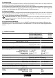
3. Anschlusshinweise 3.1. Netzanschluss und Leitungsschutz VORSICHT: Niemals bei anliegender Spannung arbeiten! Lebensgefahr! • Beim Anschluss des 3-Phasen-Netzes ist unbedingt die Klemmenbezeichnung zu beachten! • Absicherung: 25 A (Diazed) Leitungsschutz bei max.
4. Funktion 4.1. Visualisierung - Status LEDs Mit insgesamt vier LEDs visualisiert der Hybrid-Motorstarter die Betriebszustände. Die Funktionen der LEDs orientieren sich an der NAMUR-Empfehlung NE 44. • Durch eine grüne LED (PWR) wird der allgemeine Gerätestatus angezeigt. • Der Links- bzw. Rechtslauf des Antriebes wird durch jeweils eine gelbe LED (L, bzw. R) angezeigt. • Ein interner oder externer Fehler (Prozessfehler: Überstrom, Asymmetrie, Phasenausfall) wird durch eine rote LED (ERR) signalisiert.
Status Beschreibung LED: PWR ERR L R Fehlergrün rot gelb quittierung Externer Fehler in Ansteuerung oder Peripherie (Wartungsbedarf, NE44) Symmetrie: Die beiden Motorströme weichen um mehr als 33 % voneinander ab. E B A A manuell Phasenausfall: Einer der beiden gemessenen Motorströme ist Null, bzw. die Phasenverschiebung zwischen den beiden Motorströmen beträgt nicht 120° sondern 180° E B A A manuell E E B B B A A B manuell manuell Blockierung: Der max.
4.3. Parametrierung - Nennstromeinstellung • Betätigen Sie den Reset-Taster mehr als 6 s, um in den Betriebsmodus "Parametrierung" zu gelangen - die grüne LED PWR blinkt einmal auf. Zur Unterscheidung von anderen Betriebszuständen werden in der Betriebsart Parametrierung die LEDs im Abstand von 2 s für 0,3 s ausgeschaltet. • Stellen Sie den Nennstrom des Antriebs durch das 240°-Potentiometer ein. Die Nennstromvorgabe erfolgt in 16 Stufen. Die vier LEDs zeigen den eingestellten Strom an.
5.3. Motorschutz Alle für die Sicherheit relevanten Funktionen werden ohne äußeren Einfluss durch den Hybrid-Motorstarter realisiert. Besondere Schaltungstechniken sind nicht notwendig. Die Verdrahtung des Laststromkreises sollte wie in den oben aufgeführten Beispielen realisiert werden. Der Anschluss der Modulstromversorgung kann aber im Gegensatz dazu direkt an der Spannungsquelle erfolgen, ohne Sicherheitsrelais PSR. Das Gleiche gilt für die Ansteuerung. 5.4.
6. Technische Daten Nennschaltleistung nach UL 508 Full Load (power factor = 0,4) Full Load (power factor = 0,8) Leckstrom (Eingang, Ausgang) Restspannung bei Ie Stoßstrom Eingangsschutzbeschaltung Short circuit current rating SCCR nach UL 508 Rückmeldeausgang Kontaktausführung Kontaktmaterial bei Verwendung als Max. Schaltspannung Min. Schaltspannung Max. Dauerlaststrom Io Min. Schaltstrom Max. Abschaltleistung, ohmsche Last 24 V DC 48 V DC 60 V DC 110 V DC 220 V DC 250 V AC Messtechnik (bezogen auf 8.
6. Technische Daten Allgemeine Daten Verlustleistung min./max. Netzfrequenz Max. Schaltfrequenz (Puls-/Pausenzeiten 50:50) Lebensdauer Schutzart Umgebungstemperaturbereich Betrieb Transport, Lagerung Bemessungsstoßspannung zwischen Steuereingangs-, Steuerspeise- und Schaltspannung • Netznennspannung (≤ 500 V AC) • Netznennspannung (≤ 300 V AC, z.B.230/400 V AC, 277/480 V AC) • Netznennspannung (300...
ENGLISH Hybrid motor starter with reversing function ELR W3-.../500AC-...I Control input: Forward running/Reverse running Input: Control supply voltage T E: Reference point Forward running/Reverse running R L Acknowledgment inputs MAN, RES, AUT T U s Feedback 9 7 9 6 9 5 M A N R ES A U T E T L E R UT A S S 5 U RE 9 3 N 6 1,6 MA 9 97 2,4 Potentiometer for the nominal current parameterization 7 0,8 8 0,1 x.
2. Safety regulations / Installation notes • When working on the device, observe the national safety and accident prevention regulations.
3. Connection notes 3.1. Mains connection and line protection CAUTION! Never carry out work on live parts! Danger to life! • When connecting the 3-phase network, it is essential to observe the terminal identification! • Protection: 25 A (Diazed) Line protection at a max. conductor cross section of 2.5 mm2 16 A FF (6.3 x 32 mm) Device protection 16 A (automatic device B, circuit breaker) - Short circuit (1.5 kA network) 20 A (Motor protection switch) - Short circuit (1.
4. Function 4.1. Visualization - LEDs status The hybrid motor starter displays the operating conditions with a total of four LEDs. The functions of the LEDs are based on the NAMUR recommendation NE 44. • The operating status of the relay is displayed via a green LED (PWR). • The reverse or forward running of the drive is always displayed by a yellow LED (L, R). • An internal or external error (process error: overcurrent, phase failure) is signaled by a red LED (ERR).
Status Description External error in the control or peripherals (Maintenance requirement, NE 44) Symmetry: The two motor currents deviate by more than 33 %. E B A A Manual Phase failure: One of the two measured motor currents is zero or the phase shift between the two motor currents does not equal 120°, but 180° Blockage: The maximum measurable motor current is exceeded for more than 2 s. • An error occurred during the reverse running. • An error occurred during the forward running.
4.3. Parameterization - Nominal current setting • Activate the reset button for more than 6 s to reach the operating mode "Parameterization" - the green LED PWR flashes once. The LEDs are switched off at intervals of 2 s for 0.3 s in the operating mode "Parameterization" to differentiate from other operating conditions. • Set the nominal current of the drive with the 240° potentiometer. The nominal current is specified in 16 stages. The four LEDs display the set current.
5.3. Motor Overload Protection Functions relevant for safety are realized by the hybrid motor starter without any external influences. Special switching techniques are not required. The wiring of the load current circuit should be implemented as in the above listed examples. In contrast, the module current supply, however, can be connected directly to the voltage source without a safety relay PSR. This applies for the control. 5.4.
6. Technical data Leakage current (Input, Output) Residual voltage at Ie Surge current Input protective circuit Short circuit current rating SCCR 0 mA 0 mA < 300 mV < 500 mV 100 A (t = 10 ms) 100 A (t = 10 ms) varistors varistors acc.
6. Technical data General data Power dissipation min./max. Mains frequency Max. switching frequency (pulse/pause times 50:50) Service life Degree of protection Ambient temperature range Operation Transport, storage Rated surge voltage between Control input-, rated control supply- and switching voltage • Mains nominal voltage (≤ 500 V AC) • Mains nominal voltage (≤ 300 V AC, e.g. 230/400 V AC, 277/480 V AC) • Mains nominal voltage (300...
FRANÇAIS Démarreur moteur hybride avec fonction d’inversion ELR W3-.../500AC-...I Entrée de commande : Rotation à droite/gauche Entrée : Tension d’alimentation de commande T E : point de référence Rotation à droite/gauche R L Entrées d'acquittement MAN, RES, AUT T U s Accusé de réception 9 7 9 6 9 5 M A N R ES A U T E T L E R UT A U S RES 95 3 N 6 1,6 MA 9 97 2,4 Potentiomètre de paramétrage d'intensité nominale 7 0,8 8 0,1 x.
2. Contraintes de sécurité / Instructions d'installation • Respectez les directives nationales de sécurité et de prévention des accidents pour tous les travaux sur les appareils.
3. Conseils de raccordement 3.1. Raccordement au réseau et protection de ligne ATTENTION : Ne jamais travailler sur un module sous tension ! Danger de mort ! • Lors du raccordement au réseau triphasé, reportez-vous obligatoirement au repérage de BJ ! • Fusibles : 25 A (Diazed) Protection de ligne pour section de câble max. de 2,5 mm2 16 A FF (6.
4. Fonctionnement 4.1. Visualisation - LED d'état Le démarreur moteur hybride visualise les états de fonctionnement à l'aide de 4 LED au total. Les fonctions des LED s'orientent sur la recommandation NAMUR NE 44. • Le statut général de l'appareil est affiché par une LED verte (PWR). • La rotation à gauche ou à droite du moteur est indiquée respectivement par une LED jaune (L, R). • Une erreur interne ou externe (erreur de processus : surintensité, défaillance de phase) est signalée par une LED rouge (ERR).
Etat de l'appareil Erreur externe dans la commande ou la périphérie. (Besoin de maintenance, NE 44) Description LED : PWR ERR Symétrie: Les deux intensités de moteur diverE B gent l'une de l'autre de plus de 33 %. Défaillance de phase : L'une des intensités E B moteur mesurées est zéro, ou alors le décalage de phase entre les deux intensités moteur n'est pas de 120° mais de 180°. Blocage: L'intensité moteur maximale mesurable est dépassée de plus de 2 s. Une erreur est apparue lors de la rotation à gauche.
4.3. Paramétrage - Réglage de l'intensité nominale • Actionnez le bouton Reset pendant plus de 6 s, pour accéder au mode de fonctionnement « Paramétrage » - la LED PWR verte clignote une fois. Pour faire la différence avec les autres états de fonctionnement, en mode de fonctionnement « Paramétrage », les LED sont éteintes à intervalle de 2 s pendant 0,3 s. • Réglez l'intensité nominale du moteur avec le Code Intensité nominale potentiomètre 240°.
5.3. Protection du moteur Toutes les fonctions concernant la sécurité sont réalisées sans influence extérieure générée par le démarreur moteur hybride. Aucune technique de commutation spéciale n'est nécessaire. Le câblage du circuit de puissance doit être réalisé comme sur les exemples indiqués ci-dessus. Le raccordement de l'alimentation de module peut en revanche, être réalisé directement au niveau de la source de tension, sans relais de sécurité PSR. Il en va de même pour la commande. 5.4.
6. Caractéristiques techniques Courant de fuite (entrée, sortie) Tension résiduelle à Ie Courant de choc Circuit de protection d’entrée Short circuit current rating SCCR 0 mA 0 mA < 300 mV < 500 mV 100 A (t = 10 ms) 100 A (t = 10 ms) Varistances Varistances selon UL 508 - Adapté pour l'utilisation avec des circuits ne fournissant pas plus de 5 kAeff de courant symétrique, max. 500 V - Adapté pour l'utilisation avec des circuits ne fournissant pas plus de 100 kAeff de courant symétrique, max.
6. Caractéristiques techniques Fréquence de commutation max. (temps d’impulsion/temps de pause 50:50) Durée de vie Indice de protection Plage de température ambiante Service Transport, stockage Tension de choc assignée entre Tension d‘entrée de commande, tension d’alimentation de commande assignée et tension de commutation • Tension nominale du réseaux (≤ 500 V AC) • Tension nominale du réseaux (≤ 300 V AC, par ex. .230/400 V AC, 277/480 V AC) • Tension nominale du réseaux (300...
ESPAÑOL Controlador de arranque híbrido con función inversor ELR W3-.../500AC-...I Entrada: tensión de alimentación de control Entrada de mando: giro a la derecha/izquierda GNDE: punto de referencia giro a la derecha/izquierda R L Entradas de acuse de recibo MAN, RES, AUT T U s Acuse de recibo 9 7 9 6 9 5 M A N R ES A U T E T L E R UT A S S 5 U RE 9 3 N 6 1,6 MA 9 97 2,4 Potenciómetro para parametrización de la corriente nominal 7 0,8 8 0,1 x.
2. Prescripciones de seguridad / indicaciones de instalación • Observe, en todos los trabajos a realizar en el módulo, las prescripciones nacionales de seguridad y para la prevención de accidentes. • El no considerar las prescripciones de seguridad puede tener como consecuencia la muerte, lesiones corpóreas graves o grandes desperfectos materiales. • La puesta en marcha, el montaje, la modificación y el equipamiento posterior solo pueden efectuarse por un electricista.
3. Indicaciones de conexión 3.1. Conexión a la red y protección de línea ATENCIÓN: ¡No trabajar nunca con la tensión conectada! ¡Peligro de muerte! • Para conectar la red trifásica debe observarse incondicionalmente la denominación de los bornes. • Protección por fusibles: 25 A (Diazed) Protección de línea para sección máx.
4. Función 4.1. Visualización - estado de los LEDs El controlador de arranque híbrido visualiza los estados de servicio con cuatro LED´s. Las funciones de los LED´s se rigen según la recomendación NAMUR NE 44. • Mediante un LED verde (PWR) se indica el estado general del módulo. • El giro a la izquierda o giro a la derecha del accionamiento se indica mediante un LED amarillo (L, R). • Un error interno o externo (error de proceso: sobrecorriente, falta de fase) se señaliza mediante un LED rojo (ERR).
Estado del módulo Descripción Error externo en el mando o en la periferia (necesidad de mantenimiento, NE 44) LED: PWR ERR L R Acuse de recibo Simetría: Las dos corrientes de motor difieren en más del 33 %. E B A A manual Falta de fase: Una de las dos corrientes de motor medidas es cero, o el desfasaje máximo entre las dos corrientes de motor no es de 120° sino de 180° Bloqueo: La corriente de motor máx. apreciable es sobrepasada por más de 2 s.
4.3. Parametrización - Ajuste de la corriente nominal • Accione el pulsador Reset durante más de 6 s para entrar en el modo de servicio "parametrización". Para diferenciarlo de otros estados de servicio, en el tipo de servicio parametrización, los LED´s se desconectan en lapsos de 2 s en vez de 0,3 s. • Ajuste la corriente nominal del accionamiento Código Corriente nominal mediante el potenciómetro de 240°.
5.3. Guardamotor Todas las funciones relevantes para la seguridad se realizan sin influencia exterior a través del controlador de arranque híbrido. No se precisan técnicas de circuitos especiales. El cableado del circuito de corriente de carga debe realizarse tal como se indica en los ejemplos arriba mencionados. Al contrario, la conexión de la alimentación del módulo se puede realizar directamente en la fuente de tensión, sin relé de seguridad PSR. Lo mismo es válido para el mando. 5.4.
6. Datos técnicos Tensión residual para Ie Corriente transitoria Circuito de protección de entrada Short circuit current rating SCCR < 300 mV < 500 mV 100 A (t = 10 ms) 100 A (t = 10 ms) varistores varistores según UL 508 - apto para el uso en circuitos que no entreguen más de 5 kAef de corriente simétrica, máx. 500 V - apto para el uso en circuitos que no entreguen más de 100 kAef de corriente simétrica, máx.
6. Datos técnicos Frecuencia máx. de conmutación (tiempos de impulso/tiempos de pausa 50:50) Duración Índice de protección Gama de temperatura ambiente funcionamiento transporte, almacenamiento Tensión transitoria de dimensionamiento entre Tensión de entrada de mando, tensión de alimentación de control de dimensionamiento y tensión de conexión • Tensión nominal de red (≤ 500 V AC) • Tensión nominal de red (≤ 300 V AC, por ej. 230/400 V AC, 277/480 V AC) • Tensión nominal de red (300...
РУССКИЙ Комбинированный пускатель электродвигателя с функцией поворота ELR W3-.../500AC-...I Управляющий вход: Вращение по/против часовой стрелки Вход: Напряжение питания цепи управления T E: Опорный потенциал Вращение по/против часовой стрелки R L Входы квитирования MAN, RES, AUT T U s Обратная сигнализация 9 7 9 6 9 5 M A N R ES A U T E T 7 0,8 8 0,1 x.
2. Требования по технике безопасности / указания по монтажу • При выполнении любых работ с оборудованием соблюдайте требования государственных нормативных документов, регулирующих вопросы безопасности и предотвращения несчастных случаев.
Область применения: • Цепи в зонах 21 или 22, в которых существует опасность взрыва пылевоздушной смеси, должны подключаться только в том случае, если гарантируется, что оборудование, подключенное к цепи, соответствует категории 2D или 3D или прошло соответствующую сертификацию. • Данное изделие предназначено для условий A (промышленное использование).
4. Функция 4.1. Визуализация – светодиоды состояния Посредством четырех светодиодов комбинированный пускатель электродвигателя отображает рабочие состояния. Функции светодиодов соответствуют рекомендациям NAMUR NE 44. • Посредством зеленого светодиода (PWR) отображается общее состояние устройства. • Левое/правое вращение привода отображается посредством желтого светодиода (L, R).
Состояние Описание Светодиод: PWR ERR L Внешняя ошибка в Симметрия: Оба тока электродвигателя управлении или отличаются друг от друга на более чем 33 %. ошибка фазы: Один из двух измеренных токов периферийного электродвигателя равен нулю или, устройства соответственно, сдвиг фаз между обоими (Необходимость токами электродвигателя составляет не 120°, а технического 180°. обслуживания, Блокировка: Макс. измеряемый ток NE44) двигателя превышен на более чем 2 с.
4.3. Параметрирование – заданный номинальный ток двигателя • При нажатии кнопки сброса более 6 секунд для перехода в режим работы «Параметрирование» однократно мигает зеленый светодиод PWR. Для отличия от других рабочих состояний в режиме работы «Параметрирование» светодиоды отключаются на 0,3 секунды с интервалом в 2 секунды. • С помощью 240°-потенциометра настроить номинальный ток привода. Настройка номинального тока происходит 16-ти ступенчато.
5.3. Защита электродвигателя Все функции, необходимые для обеспечения безопасности, реализуются комбинированным пускателем электродвигателя без постороннего влияния. Особая коммутационная техника не требуется. Разводку цепи нагрузки тока следует выполнять согласно приведенным выше примерам. Подключение блока питания модуля можно осуществлять непосредственно к источнику напряжения без использования предохранительного реле PSR. Тоже самое относится и к управлению. 5.4.
6. Технические данные Выходные данные Способ коммуникации Цепь нагрузки ELR...-2I ELR...-9I Защитный выходной каскад с байпасом, трехфазное гальванически развязанное отключение Расчетное рабочее напряжение Ue 500 В перем. тока 500 В перем. тока согласно МЭК 60947-1 Диапазон рабочих напряжений согласно МЭК 60947-1 42 ... 550 В перем. тока 42 ... 550 В перем. тока согласно UL 508 42 ... 500 В перем. тока 42 ... 500 В перем. тока Ток нагрузки при 20 °C 0,18...2,4 A 1,2... 9,0 A (см. 8.
6. Технические данные Измерительная техника (относительно 8.1 характеристики срабатывания) Двухфазное измерение тока Диапазон Контроль симметрии Величина (Iмакс.- Iмин.)/ Iмакс. Время срабатывания Блокировочная защита I(L1), I(L3) typ. Величина (угол(L1, L3)) Время срабатывания Блокировочная защита I(L1) или I(L3) Время срабатывания Характеристика срабатывания (см. 8.2.
6. Технические данные Расчетное импульсное напряжение между выходом обратного сигнала и коммутационным напряжением (Номинальное напряжение сети: • ≤ 500 В перем. тока • ≤ 300 В перем. тока, например, 230/400 В перем. тока, 277/480 В перем. тока • 300...500 В перем. тока) Расчетное импульсное напряжение между входным управляющим напряжением, напряжением питания цепи управления и коммутационным напряжением (Номинальное напряжение сети: • ≤ 500 В перем.
7.
7.2.
8. Anhang / Appendix / Annexe / Apéndice / Приложение Auslösezeit / Release time / Temps de retombée / Tiempo de disparo [s] Время срабатывания при [с] 8.1. Auslösekennlinie bei 20 °C [1] Trigger characteristic curve at 20°C [1] Courbe de déclenchement à 20 °C [1] Curva característica de disparo para 20 °C [1] Характеристики срабатывания при 20 °C 200 100 [1] Class 10A / Класс 10A 60 40 30 20 Max. 10 6 4 3 2 Min.
8.2. Deratingkurven bei 100 % Einschaltdauer (Weitere Daten auf Anfrage) Derating curves for 100% operating time (more data available on request) Courbes de derating à 100 % de la durée d'enclenchement (autres données sur demande) Curvas derating para duración de conexión del 100 % (otros datos bajo consulta) Кривые изменения характеристик при 100%-ной продолжительности включения (дополнительные данные – по запросу) ELR W3-24DC/...
8.3. Schaltbeispiel / Example circuit / Exemple de circuit / Ejemplo de circuito / Пример схемы "NOT-HALT (zweikanalig)" - (nach Kat. 3, SIL 3, PL e): ELR W 3-.../500AC-... mit übergeordneter Sicherheitsrelais-Kombination. Zum Erreichen der maximalen Lebensdauer, falls möglich Beispiel von Seite 55 anwenden! "EMERGENCY STOP (two channels)" - (acc. to Cat. 3, SIL 3, PL e): ELR W 3-.../500AC-... with a higher-level safety relay combination.
8.4. Schaltbeispiel / Example circuit / Exemple de circuit / Ejemplo de circuito / Пример схемы "Schutztür / Zweihand-/NOT-HALT-Applikation (zweikanalig)" - (nach Kat. 3, SIL 3, PL e): ELR W 3-.../500AC-... mit übergeordneter Sicherheitsrelais-Kombination "Safety door / two-hand / EMERGENCY STOP application (two channels)" (acc. to Cat. 3, SIL 3, PL e): ELR W 3-.../500AC-...
PHOENIX CONTACT GmbH & Co. KG D-32823 Blomberg, Germany Fax +49-(0)5235-341200 Phone +49-(0)5235-300 www.phoenixcontact.