
User manual

DEUTSCH ENGLISH FRANÇAIS ESPAÑOL
Industrial modem
PSI-GPRS/GSM-MODEM/RS232-QB
Order No.: 2313106
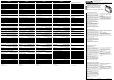
1. Operating elements
(Fig. 1a):
2. Hardware installation
2.1. Factory default configuration (Fig. 1b)
The modem is preconfigured in the factory for dial operation.
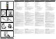
2.2. Mechanical assembly (Fig. 2)
To assemble, the modem is simply snapped onto a 35 mm EN mounting rail. The
mounting rail must be connected to PE. Only assemble or disassemble the
modules when they are in an off load state!
2.3. RS-232 interface (6 - Fig. 3)
The data connection between the modem and a computer or another device can
be established most simply using the RS-232 cable PSM-KA-9SUB 9/BB/2 ME-
TER (Order No.: 2799474). This is an interface cable with 1:1 connected con-
tacts. Connect the modem to a free COM port of the computer.
The modem may only be connected to devices that fulfill the requirements of EN
60950 (Safety of information technology equipment).
2.4. SIM Card
You must open the housing in order to access the internal SIM card holder. To
do so, unlock the top of the housing using a screwdriver (Fig. 5a). Then carefully
pull out the PCB as far as possible (Fig. 5b).
The GSM service provider will provide you with a SIM card on which all the im-
portant data of your connection are stored.
Turn the contact surface in such a way that it faces the PCB and push the SIM
card into the tray. The angled corner must face to the rear (Fig. 5b).
The SIM card can be protected via a 4 or 5 digit PIN.
We recommend to enter the PIN as described in chapter
"4.3 Configuration Software” of the user manual.
For a fast startup, the PIN can be disabled using a mobile phone (see
user manual of the mobile phone).
For further notes regarding suitable SIM cards, please refer to chapter
"3 Hardware Installation” of the user manual.
2.5. Supply voltage (Fig. 6)
The PSI-GPRS/GSM-MODEM/RS232-QB module is designed solely for opera-
tion with safety extra-low voltage (SELV) in acc. with IEC 60950 / EN 60950 /
VDE 0805.
The supply voltage is connected to 24 V and 0 V at the pluggable screw terminal
block. As soon as the VCC LED lights up, the modem is ready for operation.
2.6. Two switching inputs (Fig. 6)
The switching inputs are connected to "IN1" and "IN2" with 10 to 30 V DC. The
switching inputs are on the same potential level as the supply voltage.
3. Software installation
3.1. System requirements
In principle, every device with a programmable RS-232 interface can be connec-
ted to the modem. Configuration can then be performed with a terminal program,
for example.
To use the Plug n’ Play function and the configuration software, a PC with one of
the following operating systems is necessary: Windows 95, Windows 98, Win-
dows 2000, Windows NT, Windows ME or Windows XP.
3.2. User Manual
Put the CD marked "PSI-MODEM-CONF" in CD drive of your computer.
Please select a language and then click on the icon behind the symbolized user
manual. (If this user manual file cannot be opened, it may be necessary to install
the "Acrobat Reader”. You will also find it on this CD.)
Connection terminal blocks:
1 24 V supply (10 - 30 V DC)
2 0 V supply ( 0 V)
3 IN1 Switching input 1 (10 - 30 V DC)
4 IN2 Switching input 2 (10 - 30 V DC)
Connecting plug:
5 Antenna (SMA)
6 RS-232 data interface, SUB-D 9-position
Light indicators:
7 SIM (red) ON = SIM card is missing, flashes = PIN entry necessary
8 DCD (yellow)Data carrier detected, connection established with
coresponding device
9 NET (yellow)Network reception: ON = very good, flashes = good,
flashes quickly = moderate, OFF: no network reception
0 ALR (red) Alarm sent successfully, flashes while sending
! TD (green) Transmit data for the GSM interface
" RD (yellow)Receive data for the GSM interface
§ VCC (green) flashes = supply voltage connected
Industriemodem
PSI-GPRS/GSM-MODEM/RS232-QB
Art.-Nr.: 2313106
1. Bedienelemente
(Abb. 1a):
2. Hardwareinstallation
2.1. Werkseitige Konfiguration (Abb. 1b)
Das Modem ist werksmäßig auf den GSM-Betrieb vorkonfiguriert.
2.2. Mechanischer Aufbau (Abb. 2)
Die Montage erfolgt durch Aufrasten des Modems auf eine 35mm EN-Trag-
schiene. Die Tragschiene muss mit dem PE verbunden werden. Montieren und
demontieren Sie die Module nur im spannungsfreien Zustand!
2.3. RS-232-Schnittstelle (6 - Abb. 3)
Die Datenverbindung zwischen dem Modem und einem Computer oder ande-
rem Gerät stellen Sie am einfachsten mit dem RS-232-Kabel PSM-KA-9SUB 9/
BB/2 METER (Art.-Nr.: 2799474) her. Es handelt sich hierbei um ein Schnittstel-
lenkabel mit 1:1 verbundenen Kontakten. Verbinden Sie das Modem mit einer
freien COM-Schnittstelle des Computers.
Das Modem darf nur an Geräte angeschlossen werden, die die Bedingungen
der EN 60950 erfüllen (Sicherheit von Einrichtungen der Informationstechnik).
2.4. SIM-Karte
Sie müssen das Gehäuse öffnen, um an den innenliegenden SIM-Kartenhalter
zu gelangen. Entriegeln Sie dazu den Gehäusekopf mit einem Schraubendreher
(Abb. 5a). Ziehen Sie anschließend die Leiterplatte vorsichtig bis zum Anschlag
heraus (Abb. 5b).
Vom GSM-Dienstanbieter (Provider) erhalten Sie eine SIM-Karte, auf der alle
wichtigen Daten Ihres Anschlusses gespeichert sind.
Richten Sie die Kontaktfläche zur Leiterplatte und schieben Sie die SIM-Karte in
die Aufnahme. Die abgeschrägte Ecke muss nach hinten zeigen (Abb. 5b).
Die SIM-Karte kann mit einer vier- oder fünfstelligen PIN geschützt sein.
Wir empfehlen, die PIN wie Kapitel "4.3 Konfigurations-Software"
des Handbuches beschrieben, einzugeben.
Für eine Schnellinbetriebnahme kann die PIN mit Hilfe eines Mobiltele-
fons deaktivert werden (siehe Bedienungsanleitung des Telefons).
Weitere Hinweise zu geeigneten SIM-Karten erhalten Sie im Kapitel "3.
Hardware-Installation" des Handbuches.
2.5. Versorgungsspannung (Abb. 6)
Das Modul PSI-GPRS/GSM-MODEM/RS232-QB ist ausschließlich für den Be-
trieb mit Sicherheitskleinspannung (SELV) nach IEC 60950 / EN 60950 / VDE
0805 ausgelegt. Die Versorgungsspannung wird an der steckbaren Schraub-
klemme an 24V und 0V angeschlossen. Sobald die VCC-LED leuchtet, ist das
Modem betriebsbereit.
2.6. Zwei Schalteingänge (Abb. 6)
Die Schalteingänge werden an den steckbaren Schraubklemmen "IN1" und
"IN2" mit 10 bis 30 V DC angeschlossen. Die Schalteingänge sind zur Versor-
gungsspannung potenzialgebunden.
3. Softwareinstallation
3.1. Systemvoraussetzungen
Im Prinzip können Sie jedes Gerät mit einer programmierbaren RS-232-Schnitt-
stelle mit dem Modem verbinden. Die Konfiguration kann dann z.B. mit einem
Terminalprogramm erfolgen.
Zur Nutzung der Plug n’ Play-Funktion und der Konfigurationssoftware ist ein PC
mit einem der folgenden Betriebssysteme notwendig: Windows 95, Windows
98, Windows 2000, Windows NT, Windows ME oder Windows XP.
3.2. Handbuch
Legen Sie die CD mit der Aufschrift "PSI-MODEM-CONF" in das CD-Laufwerk
Ihres Rechners. Wählen Sie bitte eine Sprache und klicken danach auf das Icon
hinter dem symbolisierten Handbuch.
(Sollte sich das Handbuch nicht öffnen, muss möglicherweise der "Acrobat Rea-
der" installiert werden, der sich ebenfalls auf der CD befindet.)
Anschlussklemmen:
1 24 V Versorgung (10 - 30 V DC)
2 0 V Versorgung ( 0 V)
3 IN1 Schalteingang 1 (10 - 30 V DC)
4 IN2 Schalteingang 2 (10 - 30 V DC)
Anschlussstecker:
5 Antenne (SMA)
6 RS-232 Datenschnittstelle, SUB-D 9 polig
Leuchtanzeigen:
7 SIM (rot) an = SIM-Karte fehlt, blinkt = PIN-Eingabe erforderlich
8 DCD (gelb) Datenträger erkannt, Verbindung zur Gegenstelle aufgebaut
9 NET (gelb) Netzempfang: an = sehr gut, blinkt = gut,
blinkt schnell = mäßig, aus = kein Netzempfang
0 ALR (rot) Alarmmeldung wurde erfolgreich abgesendet,
blinkt während des Absendens
! TD (grün) Sendedaten bezogen auf die GSM-Schnittstelle
" RD (gelb) Empfangsdaten bezogen auf die GSM-Schnittstelle
§ VCC (grün) blinkt = Versorgungsspannung liegt an
Modem industriel
PSI-GPRS/GSM-MODEM/RS232-QB
Référence : 2313106
1. Organes de commande
(Fig. 1a)
2. Installation du matériel
2.1. Configuration en usine (Fig. 1b)
Le modem a été préconfiguré en usine pour fonctionner sur le réseau commuté.
2.2. Construction mécanique (Fig. 2)
Le montage du modem s’effectue par encliquetage sur un rail DIN de 35 mm. Le
profilé doit être relié à la terre PE. Pour monter ou démonter un module, il est
impératif de mettre celui-ci hors tension !
2.3. Interface RS 232 (6 - Fig. 3)
La liaison de données entre le modem et un ordinateur (ou un autre appareil)
peut s’établir simplement à l’aide du câble RS-232 PSM-KA-9SUB 9/BB/2
METER (Référence 2799474). Il s’agit d’un câble d’interface dont les contacts
sont câblés ’broche à broche’. Le modem se branche sur un port COM libre de
l’ordinateur. Le modem doit être raccordé exclusivement aux appareils
répondant à la norme EN 60950 (sécurité des installations informatiques).
2.4. Carte SIM
Le boîtier doit être ouvert pour accéder au porte-carte SIM se trouvant à
l'intérieur. Déverrouiller pour cela la tête du boîtier avec un tournevis (fig. 5a).
Extraire ensuite avec précaution et à fond le circuit imprimé (fig. 5b).
Le prestataire de services GSM (Provider) fournit une carte SIM sur laquelle
toutes les données importantes de votre raccordement sont mémorisées.
Tourner la surface de contact vers le circuit imprimé et insérer la carte SIM dans
sa réception. Le coin biseauté doit indiquer vers l'arrière (fig. 5b).
La carte SIM peut être protégée par un code PIN de quatre ou cinq chiffres.
Nous recommandons de saisir le code PIN comme décrit au
chapitre « 4.3 Logiciel de configuration » du manuel.
Le PIN peut être désactivé à l'aide d'un téléphone portable pour
accélérer la mise en service (voir le mode d'emploi du téléphone).
Vous obtiendrez de plus amples informations sur les cartes SIM
adéquates au chapitre « 3. Installation du matériel » du manuel.
2.5. Tension d’alimentation (Fig. 6)
Le module PSI-GPRS/GSM-MODEM/RS232-QB a été conçu pour être alimenté
exclusivement en basse tension de sécurité (SELV) d’après CEI 60950 /
EN 60950 / VDE 0805.
La tension d’alimentation se raccorde au potentiel 24 V et 0 V, à l’aide de la
borne à vis enfichable. Dès que la LED VCC s’allume, le modem est prêt pour la
communication de donnée.
2.6. Deux entrées de couplage (Fig. 6)
Les entrées de couplage se raccordent sur les bornes à vis enfichable « IN1 » et
« IN2 » sous 10 à 30 V DC. Les entrées de couplage se trouvent sur le même
niveau de potentiel comme la tension d’alimentation.
3. Installation du logiciel
3.1. Système
En principe, vous pouvez brancher le modem sur tout appareil muni d’une
interface RS-232 programmable. La configuration peut alors s’effectuer à l’aide
d’un programme de terminal.
La mise en œuvre de la fonction Plug n’ Play et du logiciel de configuration
nécessite un PC avec l’un des systèmes d’exploitation suivants : Windows 95,
Windows 98, Windows 2000, Windows NT, Windows ME ou Windows XP.
3.2. Manuel
Insérer le CD portant l'inscription « PSI-MODEM-CONF » dans le lecteur CD de
votre ordinateur. Sélectionner une langue et cliquer ensuite sur l'icône derrière
le symbole de manuel.
(Si le manuel ne devait pas s'ouvrir, il faudra le cas échéant installer l'« Acrobat
Reader » qui se trouve également sur le CD).
Bornes de raccordement :
1 alimentation 24 V (10 - 30 V DC)
2 alimentation 0 V (0 V)
3 IN1 entrée de couplage 1 (10 - 30 V DC)
4 IN2 entrée de couplage 2 (10 - 30 V DC)
Connecteurs :
5 Antenne (SMA)
6 Interface de données RS-232, SUB-D 9 broches
Signalisations lumineuses :
7 SIM (rouge) allumée = carte SIM manque,
clignote = saisie de PIN nécessaire
8 DCD (jaune) porteuse détectée, liaison établie avec la station opposée
9 NET (jaune) réception du réseau : allumée = très bonne,
clignote = bonne, clignote rapidement = moyenne,
éteint = pas de réception du réseau
0 ALR (rouge) message d’alarme envoyé, clignote pendant l’envoi
! TD (vert) données envoyées sur le interface GSM
" RD (jaune) données reçues sur le le interface GSM
§ VCC (vert) clignote = alimentation présente
Modem industrial
PSI-GPRS/GSM-MODEM/RS232-QB
Código: 2313106
1. Elementos de operación
(Fig. 1a)
2. Instalación del hardware
2.1. Configuración de fábrica (Fig. 1b)
El modem está configurado previamente en fábrica para el servicio automático.
2.2. Instalación mecánica (Fig. 2)
El montaje se efectúa mediante encaje del modem sobre un carril EN de
35 mm. El carril tiene que conectarse con la tierra PE.
¡Montar y desmontar los módulos únicamente en estado sin tensión!
2.3. Interface RS-232 (6 - Fig. 3)
La comunicación de datos entre el modem y un ordenador u otro equipo se re-
aliza de la forma más fácil con el cable RS-232 PSM-KA-9SUB 9/BB/2 METER
(Código 2799474). El cable mencionado es un cable interface con contactos
conectados 1:1. Conecte el modem a un interface COM libre del ordenador.
El modem debe conectarse solo a aparatos que satisfacen las condiciones de
la norma EN 60950 (seguridad de dispositivos de la técnica de información).
2.4. Tarjeta SIM
Hay que abrir la carcasa para acceder al portatarjetas SIM situado en el interior.
A tal efecto, desbloquee la cabecera de la carcasa con un destornillador (Fig.
5a). A continuación, extraiga la placa de circuito impreso con cuidado hasta el
tope (Fig. 5b).
Del proveedor de GSM recibirá una tarjeta SIM en la que están almacenados
todos los datos importantes de su conexión.
Oriente la superficie de contacto hacia la placa de circuito impreso e inserte
la tarjeta SIM en el soporte. La esquina biselada debe señalar hacia atrás
(Fig. 5b).
La tarjeta SIM puede estar protegida por un PIN de cuatro o cinco dígitos.
Recomendamos introducir el PIN, tal y como se describe en el
capítulo "4.3 Software de configuración" del Manual.
Para una puesta en servicio rápida puede desactivarse el PIN con
ayuda de un teléfono móvil (ver las instrucciones de servicio del
teléfono).
Para obtener más datos sobre tarjetas SIM adecuadas, consulte el
capítulo "3. Instalación del hardware" del Manual.
2.5. Tensión de alimentación (Fig. 6)
El modem PSI-GPRS/GSM-MODEM/RS232-QB se ha dimensionado exclusi-
vamente para el funcionamiento con tensión baja de seguridad (SELV) según
IEC 60950 / EN 60950 / VDE 0805.
La tensión de alimentación se conecta al borne enchufable de tornillo a 24V y
0V. Cuando se enciende el VCC-LED, el modem está listo para la comunicación
de datos.
2.6. Dos entradas de conmutación (Fig. 6)
Las entradas de conmutación se conectan al bornes enchufable de tornillo "IN1"
y "IN2" con 10 hasta 30 V DC. Las entradas de conmutación se encuentran en
el mismo nivel de potencial como la tensión de alimentación.
3. Instalación del software
3.1. Condiciones del sistema
Por regla general, el modem puede conectarse con cualquier aparato equipado
con un interface RS-232 programable. Luego, la configuración se realiza, p.ej.
con un programa terminal.
Para utilizar la función "plug n’ play" y el software de configuración es necesario
un PC equipado con uno de los siguientes sistemas operativos: Windows 95,
Windows 98, Windows 2000, Windows NT, Windows ME o Windows XP.
3.2. Manual
Inserte el CD titulado "PSI-MODEM-CONF" en la unidad de CD de su
ordenador. Por favor, seleccione un idioma y, después, haga clic en el icono
situado detrás del manual simbolizado.
(En el caso de no abrirse el manual, posiblemente haya que instalar el programa
"Acrobat Reader", también incluido en el CD).
Bornes de conexión:
1 Alimentación de 24 V (10 - 30 V DC)
2 Alimentación 0 V ( 0 V)
3 IN1 entrada de conmut. 1(10 - 30 V DC)
4 IN2 entrada de conmut. 2 (10 - 30 V DC)
Conector de conexión:
5 Antena (SMA)
6 Interface de datos RS-232, SUB-D 9 polos
Indicaciones luminosas:
7 SIM (rojo) encendido = tarjeta SIM falta,
intermitente = introducción PIN necesaria
8 DCD (amarillo) soporte de datos identificado, comunicación a la estación remota
9 NET (amarillo)recepción de red: encendido = muy buena,
intermitente = buena, parpadeo rápido = regular,
descendido = no hay recepción de red
0 ALR (rojo) aviso de alarma emitido con éxito, parpadea durante la emisión
! TD (verde) datos de transmisión referidos a la interface GSM
" RD (amarillo)datos de recepción referidos a la interface GSM
§ VCC (verde) parpadea = hay tensión de alimentación
>
A
B
Abb./Fig. 4
7174A002
Abb./Fig. 2
PSI-GPRS/GSM-
MODEM/RS232-QB
Ord.-No. 23 13 106
RS 232
NET
DCD
ALR
SIM
VCC
RD
ANT
5
12 34
5
§
"
!
0
9
8
7
Abb./Fig. 1
6
PSI- GSM-
MODEM/RS232-QB
Ord.-No. 23 13 106
GPRS/
VCC
RD
ALR
NET
DCD
SIM
ANT
B
A
A
Abb./Fig. 5bAbb./Fig. 5a
323
232
747
858
420 4
666
575
TxD
RxD
RTS
CTS
DTR
DSR
GND
TxD
RxD
RTS
CTS
DTR
DSR
GND
SUB D
25 9
SUBD9
max.
15 m
922 9
RI RI
181
DCD DCD
PC / SPS Modem
7174A003
Abb./Fig. 3
24V 0V IN1 IN2
24 V IN2
0 V IN1
Abb./Fig. 6