User manual UM EN PSI-MODEM-SHDSL/SERIAL Order No.
User manual SHDSL SERIAL permanent line modem, for point-to-point, line, and star structures on in-house cables 2011-12-06 Designation: UM EN PSI-MODEM-SHDSL/SERIAL Revision: c00 Order No.: — This user manual is valid for: Designation PSI-MODEMSHDSL/SERIAL 104275_en_c00 Revision Order No.
Please observe the following notes User group of this manual The use of products described in this manual is oriented exclusively to: – Qualified electricians or persons instructed by them, who are familiar with applicable standards and other regulations regarding electrical engineering and, in particular, the relevant safety concepts. – Qualified application programmers and software engineers, who are familiar with the safety concepts of automation technology and applicable standards.
General terms and conditions of use for technical documentation Phoenix Contact reserves the right to alter, correct, and/or improve the technical documentation and the products described in the technical documentation at its own discretion and without giving prior notice, insofar as this is reasonable for the user. The same applies to any technical changes that serve the purpose of technical progress.
Table of contents 1 2 3 Description of the SHDSL permanent line modem ..................................................................1-1 1.1 Description ......................................................................................................... 1-1 1.2 Ordering data ..................................................................................................... 1-2 1.3 Technical data ...............................................................................................
PSI-MODEMSHDSL/SERIAL 4 5 Optimization ............................................................................................................................4-1 4.1 Optimizing the SHDSL data rate......................................................................... 4-1 4.2 Increasing immunity to interference .................................................................... 4-2 Eliminating errors ..............................................................................................
Description of the SHDSL permanent line modem 1 Description of the SHDSL permanent line modem 1.1 Description The industrial SHDSL SERIAL permanent line modem enables broadband networking of serial devices via in-house cables. Areas of application – – – – Suitable for in-house cables, not for public telephone networks Point-to-point connection Star structure Line structure (daisy chain) SHDSL technology – – – – Symmetrical data transmission 2 SHDSL ports per device Up to 30 Mbps (4-wire) Up to 15.
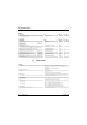
PSI-MODEMSHDSL/SERIAL 1.2 Ordering data Modem Description SHDSL permanent line modem, for point-to-point, line, and star structures on in-house 2 and 4-wire cables Accessories Description System power supply unit, primary-switched Input voltage range Nominal output voltage Nominal output current Type Order No. Pcs. / Pkt. PSI-MODEMSHDSL/SERIAL 2313669 1 Type Order No. Pcs. / Pkt. MINI-SYS-PS-100-240AC/24DC/1.5 2866983 1 45 Hz ... 65 Hz 85 V AC ... 264 V AC 24 V DC ±1% 1.
Description of the SHDSL permanent line modem SHDSL interface Status and diagnostic indicators 2 x LINK, 2 x STAT (DSL data traffic port A and port B) DIAG (yellow LED), diagnostic messages ERR (red LED), errors TERM (yellow LED), only relevant for RS-485 RS232 (yellow LED) RS-232 interface Connection method 9-pos. D-SUB plug Type RS-232 interface, according to ITU-T V.28, EIA/TIA-232, DIN 66259-1 Transmission speed Can be freely parameterized from 92 bps ... 230.
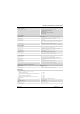
PSI-MODEMSHDSL/SERIAL General data (Fortsetzung) Electrical isolation DIN EN 50178 (Supply // RS-485, RS-422 // DSL port A // DSL port B // FE) MTBF according to Telcordia standard – – Test voltage 1004 years Telcordia standard, 25°C ambient temperature, 21% operating cycles (5 days a week, 8 hours a day) 199 years Telcordia standard, 40°C ambient temperature, 34.25% operating cycles (5 days a week, 8 hours a day) 1.5 kV AC, 50 Hz, 1 min.
Description of the SHDSL permanent line modem 1.4 SHDSL technology SHDSL (Symmetrical High-Speed Digital Subscriber Line) enables the same data transmission speeds for up and downstream via one or two double wires. Data rates of up to 15.3 Mbps are possible per cable pair. The maximum possible transmission speed greatly depends on the cable length, the cable cross section, and the cable type. 16.0 14.0 SHDSL data rate [Mbps] 12.0 11.0 PE 0.4 mm (0.13 mm²) 10.0 PE 0.9 mm (0.64 mm²) 8.0 6.0 PE 1.
PSI-MODEMSHDSL/SERIAL 1.5 Interface basics 1.5.1 RS-232 The RS-232 interface is a widely used serial interface, which is defined in standards EIA232 and CCITT V.24. This interface carries out data exchange between two devices (point-to-point connection). It transmits and receives data in full duplex mode over lines of up to 15 m. The maximum transmission speed is 230.4 kbps.
Description of the SHDSL permanent line modem 1.5.2 RS-422 The RS-422 standard supports serial data transmission in full duplex mode between two devices. In the case of the RS-422 interface, data can travel distances of up to 1200 m. Transmission speeds of up to 2000 kbps are possible. The RS-422 interface is operated with at least two data channels: transmit (T) and receive (R). DTE DTE T (A) R (A) T (B) R (B) Figure 1-3 R (A) T (A) R (B) T (B) RS-422 interface Termination resistors (100 ...
PSI-MODEMSHDSL/SERIAL 1.5.3 RS-485 W2 The RS-485 W2 interface is similar to the RS-422 interface. The electrical levels and their logical assignment are identical to those of the RS-422 standard. In addition, the RS485 W2 interface offers the option of multipoint connections. In the case of a multipoint connection, all devices are addressed and identified via a single address. Only one device may transmit at any given moment, all other devices are in "listening mode".
Description of the SHDSL permanent line modem Supported network structures Point-to-point connection RS 232 RS 422 RS 485 Figure 1-5 SHDSL 4 Wire SHDSL SHDSL 2 Wire SHDSL SHDSL 1.6.1 SHDSL 1.6 RS 232 RS 422 RS 485 RS 232 RS 422 RS 485 RS 232 RS 422 RS 485 Point-to-point connection A point-to-point connection is a direct connection between two devices without an intermediate station. Distances of over 20 km can be covered at low data rates and with good cable quality.
PSI-MODEMSHDSL/SERIAL Line structure (daisy chain) Figure 1-6 RS-485 RS-485 SHDSL RS-485 Special case, half duplex (RS-232/RS-422 and RS-485) SHDSL Standard SHDSL 1.6.2 RS 232 RS 232 RS 422 RS 485 RS 232 RS 422 RS 485 Line structure A line structure (daisy chain) is a number of components that are connected in series. Using the permanent line modem, up to 255 devices can be connected together in 2-wire operation.
Description of the SHDSL permanent line modem 1.6.3 Star structure (for all interfaces) RS-232 RS-422 RS-485 RS-232 RS-422 RS-485 Figure 1-7 Half duplex RS-232 RS-422 RS-485 Star structure (RS-232, RS-422, RS-485) The star structure in the example (Figure 1-7) consists of three modems. It is a line structure where the middle modem has been moved up to act as the head station. This means that two SHDSL ports are available at each modem.
PSI-MODEMSHDSL/SERIAL 1.6.4 Star structure via DIN rail connector and RS-485 interface In principle, a star structure via the DIN rail connector can only be used in combination with the RS-485 interface. Make sure that all devices connected via the DIN rail connector (T-BUS) use the same serial data rates. SHDSL ... SHDSL SHDSL SHDSL ...
Description of the SHDSL permanent line modem T-BUS RS-485 A5 A1 A3 A2 B2 C3 A4 C2 C1 B1 A Figure 1-10 B C Star structure with SHDSL devices (1), RS-485 on all devices In order to configure the above structure, you must proceed as follows: • Divide the overall structure into several lines (sections A, B, C) • Configure each line individually via the PSI-CONF configuration software. We recommend beginning with the critical line.
PSI-MODEMSHDSL/SERIAL Structure of a head station For the star structure, individual line structures are coupled together via a head station. In both examples above, devices A5, B2, and C3 are connected via a DIN rail connector (T-BUS). For a head station, we recommend connecting devices via the T-BUS. In this way, the segments are electrically isolated. ③ ① ④ ⑤ ② ③ ① ④ ⑤ ② T-BUS ⑥ ⑥ Not recommended (RS-485) Figure 1-12 ⑦ ⑧ Recommended (RS-485) Examples for RS-485 head stations Key ①, ②, ③ .
Description of the SHDSL permanent line modem 1.6.5 Star structure with other RS-485 components When using an RS-485 interface, the data is transmitted to the DIN rail connector (T-BUS). In this way it is possible to combine the SHDSL modems with other RS-485 components from Phoenix Contact. A combination of several different SHDSL modems (e.g., from PSI-MODEMSHDSL/SERIAL and PSI-MODEM-SHDSL/ETH) is not possible.
PSI-MODEMSHDSL/SERIAL 1.6.6 Branches and branch lines Branches and branch lines are not supported by the SHDSL modem. SHDSL only supports point-to-point communication and not multipoint communication. SHDSL ... ... SHDSL SHDSL Not possible ...
Hardware installation 2 Hardware installation Scope of supply – – – SHDSL modem CD-ROM with PSI-CONF configuration software Package slip Default settings The device is supplied with the following configuration: – Line operation – DSL: Automatic data rate detection in the range from 192 kbps to 5.696 Mbps per channel DSL port A: active DSL port B: active – Serial interface: Automatic DTE/DCE detection activated RS-232 activated, 19.
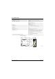
PSI-MODEMSHDSL/SERIAL 2.1 Mounting the module on a DIN rail WARNING: Only mount and remove the modem when the power supply is disconnected. NOTE: The DIN rail must be connected to PE to ensure safe operation. 2.1.1 A Mounting on a DIN rail (single device) B 101973A008 Figure 2-1 Mounting and removal (single device) Mounting: • • • Place the device onto a grounded 35 mm DIN rail from above so that the upper housing keyway hooks onto the top edge of the DIN rail (see Figure 2-1 A).
Hardware installation 2.1.2 Mounting with DIN rail connectors (connection station) By using an additional system power supply unit (MINI-SYS-PS-100-240AC/24DC/1.5, Order No. 2866983), a redundant power supply is made available for further devices connected in the connection station. Prior to assembly, two DIN rail connectors (Order No. 2709561) for each modem are inserted into the DIN rail for forwarding the power supply.
PSI-MODEMSHDSL/SERIAL 2.2 Connection terminal blocks 1 (COMBICON) 2 3 4 5/6 7/8 9 Additional interfaces 14 15 Status and diagnostic indi- 10 12 cators 1 2 3 4 5 6 7 8 PSI-MODEM-SHDSL/SERIAL Ord.-No. 23 13 669 22 21 20 9 11 13 VCC TERM DSL B DSL A LINK STAT LINK STAT USB RS232 DG RD TD ERR SERIAL RS232 19 18 17 16 10 11 12 13 14 16 17 15 18 19 Additional information about the LEDs can be found in the PSI-CONF configuration software (under device diagnostics).
Hardware installation 2.3 2.3.1 Establishing connections Safety notes WARNING: Electrical connection may only be carried out by qualified personnel The electrical connection, startup, and operation of this device may only be performed by qualified personnel. With respect to the safety notes in this document, qualified personnel are persons who are authorized to start up, to ground, and to mark devices, systems, and equipment according to the standards of safety technology.
PSI-MODEMSHDSL/SERIAL 2.3.2 DSL connection The device has two plug-in DSL connection terminal blocks, each with the connections (a) and (b). DSL port A (a) (b) (a) DSL port B (b) Figure 2-3 DSL connection NOTE: Never connect DSL port A to DSL port B on the same device (DSL loop). In order to make data transmission less susceptible to interference, we recommend using shielded twisted pair cables. You can use star-quad twisted cables.
Hardware installation 4-wire connection (line redundancy or speed increase) The 4-wire connection can be used for line-redundant operation or to increase the speed. 1 2 PSI-MODEM-SHDSL/SERIAL Ord.-No. 23 13 669 PSI-MODEM-SHDSL/SERIAL Ord.-No.
PSI-MODEMSHDSL/SERIAL 2.3.3 Connecting switching outputs In order for the switching outputs (DO/DIO) to function, the modem must be supplied with voltage via the COMBICON plug-in connectors. This is not possible when voltage is supplied via USB or the DIN rail connector. DO DIO Figure 2-7 Digital switching outputs: The modem has two digital switching outputs.
Hardware installation 2.3.4 Connecting the serial interface WARNING: The modem may only be connected to devices which meet the requirements of EN 60950 (Safety of information technology equipment). Interface basics RS-232 See "RS-232" on page 1-6 RS-422 See "RS-422" on page 1-7 RS-485 W2 See "RS-485 W2" on page 1-8 PSI-MODEM-SHDSL/SERIAL Ord.-No.
PSI-MODEMSHDSL/SERIAL RS-232 interface We recommend using shielded data cables. For devices that are connected to the RS-232 interfaces, the modem automatically switches between DCE and DTE by default. The RS-232 interface is a 9-pos. D-SUB plug. All signals except for the RI (Ring Indicator) signal are present. The interface has ground reference and is not electrically isolated from the potential of the supply voltage.
Hardware installation RS-485 W2/RS-422 interface In addition to the D-SUB plug, a 6-pos. COMBICON plug is used. The pin assignment is as follows: Assignment of the RS-485/RS-422 interface (COMBICON) RS-485 W2 RS-422 1 - R(N) 2 - R(P) 3 D(A) T(N) 4 D(B) T(P) 5 GND GND 6 Shield Shield Assignment 1 2 3 4 DG 5 RD 6 TD VCC TERM RS232 B DSL A Contact AL Table 2-2 LINK STAT LINK The interface is electrically isolated from all other isolated groups.
PSI-MODEMSHDSL/SERIAL 2.3.5 Connecting the USB interface You can configure the modem or read diagnostic information via the USB interface. Power can also be supplied via USB for configuration purposes. The "VCC" LED flashes at 1 Hz in this case. SHDSL operation is not possible. To connect the modem to a computer, use the CABLE-USB/MINI-USB-3,0M cable (Order No. 2986135). The USB interface is used to configure the modem via the PSI-CONF configuration software.
Hardware installation 2.3.6 Connecting the supply voltage WARNING: The PSI-MODEMSHDSL/SERIAL is designed exclusively for SELV operation according to IEC 60950/EN 60950/VDE 0805. The supply voltage must be between 18 V DC and 30 V DC. Supply the supply voltage to the module via the "24V" and "0V" terminal blocks or with the system power supply unit via the DIN rail connectors (T-BUS). You can supply other modules up to a maximum of 1.5 A via the device.
PSI-MODEMSHDSL/SERIAL Ambient temperature range Operation (no other modules supplied via the device): – Freestanding (40 mm spacing) -20°C ... +60°C – Connected in series (low power dissipation of modules connected in series) -20°C ... +55°C – Connected in series (without restrictions) -20°C ... +50°C Operation (other modules supplied via the device, 1.5 A, maximum) -20°C ... +45°C Storage/transport -40°C ... +85°C +24 V +24 V +24 V +24 V ³ 40 mm +24 V ... ... ... ... ... ...
Hardware installation 2.4 Use in potentially explosive areas The PSI-MODEMSHDSL/SERIAL is designed for use in potentially explosive areas that require category 3G equipment. Special conditions Observe the specified conditions for use in potentially explosive areas. WARNING: Explosion hazard Install the device in suitable housing with IP54 protection, minimum, that meets the requirements of EN 60079-15.
PSI-MODEMSHDSL/SERIAL 2-16 PHOENIX CONTACT 104275_en_c00
Configuration via PSI-CONF 3 Configuration via PSI-CONF The device is supplied with the following configuration: – Line operation – DSL: Automatic data rate detection in the range from 192 kbps to 5.696 Mbps per channel DSL port A: active DSL port B: active – Serial interface: RS-232 activated, 19.
PSI-MODEMSHDSL/SERIAL Connection requirements – – – A PC with a Windows operating system is required in order to use the configuration software. For configuration purposes, the modem can be supplied via an external power supply unit or via the USB interface. The computer that is to be used for configuration must support connection to the USB socket on the modem. Use the following USB cable for this: CABLE-USB/MINI-USB-3,0M, Order No. 2986135.
Configuration via PSI-CONF 3.2 Getting started A welcome screen appears. 3.2.1 Selecting the language PSI-CONF is started in English or German depending on the operating system. You can select the desired language. • To do this, click on "Language"/"Sprache" in the menu at the top left and select "English - Englisch", "German - Deutsch" or "Chinese Simplified". 3.2.2 • • 104275_en_c00 Selecting the device Next, select the device that you wish to configure.
PSI-MODEMSHDSL/SERIAL 3.2.3 Connection mode Connection mode Offline Local configuration For this, the computer and modem must be connected via the USB cable. Configuration is performed directly. The software switches to online mode. Configuration file You can create a new project or open an existing project. A new window appears when you click on "Configuration file". Here you can choose between "New project" or "Open project". The configuration is created and saved offline on the computer.
Configuration via PSI-CONF 3.3 Configuration Configuration (local configuration or configuration file) Point-to-point wizard Configuration of the connection between two modems. A 2 or 4-wire connection is possible. To create a star structure, please refer to the notes in Sections 1.6.3 to 1.6.5. Line structure wizard Configuration of a line structure with a 2-wire connection. A network can be configured via several steps for up to 255 devices.
PSI-MODEMSHDSL/SERIAL Configuration >> Point-to-point wizard or Line structure wizard Step 3: DSL line configuration The line already has a name (DSL line 1, etc.). You can assign a new name, e.g., "Line to hall A". The name can contain 255 characters including special characters. In the case of the point-to-point wizard, you can specify under "DSL line arrangement" whether it is a 2-wire or 4-wire line. In the case of the line structure wizard, only 2-wire lines are configured.
Configuration via PSI-CONF Configuration >> Point-to-point wizard or Line structure wizard Data transmission mode – – Character-based data transmission is suitable for protocols where the interval between individual characters on the physical layer plays a lesser role. This is the case, for example, when transmitting a file via an RS-232 interface or with the Modbus ASCII protocol. For character-based protocols, characters may also be transmitted individually or in fragments via the SHDSL modems.
PSI-MODEMSHDSL/SERIAL Configuration >> Point-to-point wizard or Line structure wizard Settings for selected device Interface type: RS-232, RS-422, RS-485 W2 Baud rate: 110 ... 2,000,000 bps Parity: None, Even, Odd, Mark, Space Stop bits: 1, 1.5 or 2 Data bits: 7 or 8 DCE/DTE Switchover (RS-232 only): Automatic, DCE (device is modem), DTE (device is PC). For information on DCE/DTE switchover, please refer to "RS-232 interface" on page 2-11.
Configuration via PSI-CONF Configuration >> Point-to-point wizard or Line structure wizard Step 5: IO configuration Click on "Edit" to change the default settings. The following window appears. Under certain conditions (signal quality is no longer good/very good or the DSL or serial connection was interrupted), the DO/DIO can be set to "24 V" or "open". The diagnostic LED lights up if a serious error is detected. In this case, we recommend reading the diagnostic memory (see "Event log" on page 3-13).
PSI-MODEMSHDSL/SERIAL Configuration >> Point-to-point wizard or Line structure wizard Step 7: Transfer Online mode is activated automatically for the transfer. • Select the first configured device and connect it via the USB cable. • Wait until communication is established with the device. A window containing a progress bar appears briefly. • Click on "Transfer" to transfer the data to the device connected via USB.
Configuration via PSI-CONF 3.3.1 Setting default settings Configuration >> Set default settings Set default settings This function is only available in online mode. The device is supplied with the following configuration: – Line operation – DSL: Automatic data rate detection in the range from 192 kbps to 5.696 Mbps per channel DSL port A: active DSL port B: active – Serial interface: RS-232 activated, 19.
PSI-MODEMSHDSL/SERIAL 3.4.1 Diagnostic overview Diagnostics >> Device status >> Diagnostic overview Device information 3-12 PHOENIX CONTACT Type The designation clearly identifies the type of the selected device. The designation is also printed on the device. Order No. The order number can be used to clearly identify the device type. You can use this number to search for additional information and downloads for this device on the Phoenix Contact website. The order number is printed on the device.
Configuration via PSI-CONF Diagnostics >> Device status >> Diagnostic overview Serial interface Data rate The speed of the serial connection. Status RS-232 connection Status of the RS-232 connection. Flowcontrol Status of flow control. Port A Indicates whether serial data is received via DSL connection A. Errors are also indicated. Port B Indicates whether serial data is received via DSL connection B. Errors are also indicated. D-SUB 1. 2. 3. 4. 5. 6. 7. 8. 9. No data reception. Data is received.
PSI-MODEMSHDSL/SERIAL Diagnostics >> Device status >> Diagnostic overview 12. A large number of data packets contain errors relating to the stop bit. Check whether the following device settings are correct and correspond to the data to be transmitted: – Parity – Data bits (7 or 8 bits) – Stop bits – Data rate 13. Software buffer overflow. The data is being received via the SHDSL interface faster than it can be output to the serial interface.
Configuration via PSI-CONF 3.4.2 Event log The event log can be printed or exported as a ".csv" file via the "Export" button. Diagnostics >> Event log Event log 104275_en_c00 Type The type of event. Possible values include: "Error", "Warning" or "Information". Time based on PC clock Date and time of the event (based on the PC clock). ID The event ID. The IDs of diagnostic messages are described under "Diagnostic IDs" on page 5-1. Event description The description of the event.
PSI-MODEMSHDSL/SERIAL 3.4.3 Value log The value log can be printed or exported as a ".csv" file via the "Export" button. Diagnostics >> Value log Value log Type The type of event. Possible values include: – Cyclic value: a value is recorded every 3 minutes – Event: only recorded when an event occurs Time based on PC clock Date and time of the event (based on the PC clock). Port A/B Data rate The speed of the SHDSL connection. The lower the data rate, the greater the distance of the DSL line.
Configuration via PSI-CONF Diagnostics >> Value log Remote port A/B status Indicates the status of the serial connection via remote port A/B of the device. RS-232 connection status Indicates the status of the serial connection via the RS-232 interface. 3.5 Transfer Transfer Open file and write to device or Read configuration and save to file This function is only available in online mode. There are two options: 1. You can open an existing file and save it to the modem connected via USB. 2.
PSI-MODEMSHDSL/SERIAL 3.6 Firmware update NOTE: The device must not be disconnected from the PC or the power supply during a firmware update as this can cause damage to the device. In order to benefit from a wider range of functions, you can download the latest firmware at www.phoenixcontact.net/catalog and transfer it to your device. To update the firmware, you must switch to online mode.
Optimization 4 Optimization 4.1 Optimizing the SHDSL data rate The cable length and cable cross section have a major influence on the SHDSL data rate. In turn, the SHDSL data rate influences the maximum possible serial data rate. The PSI-CONF configuration software calculates the expected SHDSL data rate from the cable length and cable diameter. The SHDSL data rate determined in this way is the basis for the maximum serial data rate.
PSI-MODEMSHDSL/SERIAL 4.2 Increasing immunity to interference If the SHDSL cables are subject to strong external sources of interference, you should further increase the immunity to interference of data transmission. This means that the lower the SHDSL data rate, the higher the immunity to interference. The lower the serial data rate, the lower the required SHDSL data rate and the more immune the system is to interference. Therefore, for your application, select the lowest possible serial data rate.
Eliminating errors 5 Eliminating errors 5.1 Table 5-1 Diagnostic IDs Diagnostic IDs No. Meaning Event 001 Flash memory defective LED Possible cause(s) Remedy VCC LED and ERR LED are blinking (2 Hz) Flash memory partly defective Replace device ERR LED and DIAG LED on The device is configured in 4-conductor mode, however, two different devices are recognized which are connected via SHDSL.
PSI-MODEMSHDSL/SERIAL Table 5-1 Diagnostic IDs No. 007 Meaning Link quality sufficient 008 Devices connected as a ERR LED and ring DIAG LED on 009 Error when booting the SHDSL controller 010 011 012 013 014 015 016 017 018 5-2 LED DSL STAT LED pulsing (short flashes every 3 s) Possible cause(s) The link quality was specified as "sufficient" which is due to 1. Massive interference, high crosstalk to another cable 2. A too high data rate 3. A too long/poor cable Remedy 1.
Eliminating errors Table 5-1 Diagnostic IDs No.
PSI-MODEMSHDSL/SERIAL Table 5-1 No. 025 026 027 Diagnostic IDs Meaning LED Massive noise on the se- ERR LED and rial interface DIAG LED on Device initialization error ERR LED and DIAG LED on Software buffer overflow. ERR LED and DIAG LED on Possible cause(s) Remedy On the serial interface there are Check if the correct data rate is many too short periods of "zeros". configured. Cause: Incorrect data rate configured (actual data rate is higher than that of the device).
Eliminating errors Table 5-1 Diagnostic IDs No. 088 Meaning LED Link state changed from – "Link partner found" to "Link is down" 089 Link state changed from DSL LINK LED "Initializing" to "Link is pulsing (short down" flashes every 3 s) 090 Link state changed from – "Link established" to "Link is down" 091 Link quality is good 092 093 094 reserved reserved reserved 104275_en_c00 – Possible cause(s) 1. Connector was unplugged while the link was established. 2. Link partner had a power failure.
PSI-MODEMSHDSL/SERIAL Table 5-1 Diagnostic IDs No. 095 Meaning LED RS-232 interface no lon- – ger connected Possible cause(s) – The RS-232 line was removed – The connected RS-232 device was removed – Power failure of the connected RS-232 device 096 Sporadic parity errors – Sporadically, parity errors occur on the serial interface. 096 Sporadic stop bit errors – 097 Sporadic protocol violations – 098 Sporadic noise – 100 There is no more data re- – ceived from the remote device(s).
Eliminating errors Table 5-1 No. 101 Diagnostic IDs Meaning LED There is no more data re- – ceived from the serial interface. Possible cause(s) Remedy For one minute there was no data Determining the moment of a local received from the serial interface. communication interruption. Although data was received previously. There has been interference at a – port which no longer occurs.
PSI-MODEMSHDSL/SERIAL Table 5-1 Diagnostic IDs No. 186 Meaning LED Possible cause(s) Remedy Device supplied via USB VCC LED blink- This message is generated when – port only ing (1 Hz) the device is supplied via the USB port only. No data traffic may take place, since the DSL chip is reset to save energy. 187 DIAG LED set DIAG LED on An error event caused the DIAG LED to be set. – 188 DIAG LED reset DIAG LED off The DIAG LED was reset (automatically or manually).
Eliminating errors Table 5-1 Diagnostic IDs No. 201 Meaning Interface receives data LED – 202 No more collisions on the – RS-485 interface. 203 No more parity errors. – 204 No more stop bit errors. – 205 No overloading of the SHDSL line anymore. – 206 Data is received from the – SHDSL port. 207 No more inconsistent de- – vice configuration detected. 208 No more noise. 209 No protocol violations on – the serial interface anymore. 210 No overflow of the buffer – detected.
PSI-MODEMSHDSL/SERIAL 5-10 PHOENIX CONTACT 104275_en_c00