
Datasheet


PSR-PS21
106253_en_00 PHOENIX CONTACT 11
10 Mounting and connection
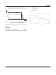
Mount the module on a 35 mm DIN rail according to
EN60715.
Figure 8 Mounting and removing
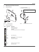
Connect the cables to the connection terminal blocks using
a screwdriver.
Figure 9 Connection of the cables
11 Startup
Apply the rated control supply voltage at terminal blocks A1/
A2. The PWR LED and K1 LED light up.
Enabling current path 13/14 closes, and confirmation cur-
rent path 21/22 opens.
12 Proof test
In the proof test, you check the individual relay channels.
1. Activate A1/A2.
2. Apply the 24VDC diagnosis power supply to con-
tact21.
If the green DGN-LED lights up, the module is functional.
(Apply 24VDC to signal output M1.)
If the red ERR LED lights up, replace the module.
(Apply 0VDC to signal output M1. Error acknowledgment
via A1 is inactive.)
If the diagnostic voltage supply is present and the green
DGN LED and the red ERR LED are on, replace the module.
If the diagnostic voltage supply is present but neither of the
LEDs specified is on, replace the module.
For compliance with UL approval, use copper
wire that is approvedupto 60°C/75°C.
A
B
0,5-0,6 Nm
5-7 lb In
12 mm
AWG 26-12
0,2-2,5 mm
2
Replace the device in the event of an error.