
Datasheet


PSR-MC30
106173_en_01 PHOENIX CONTACT 7
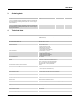
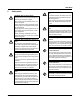
6 Basic circuit diagram
Figure 1 Block diagram
Key:
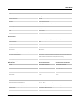
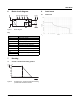
7Derating
7.1 Vertical or horizontal mounting position
Figure 2 Derating curve - vertical or horizontal mounting
position with connected modules
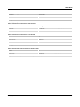
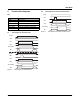
8Load curve
8.1 Ohmic load
Figure 3 Lastkurve Relais - ohmsche Last
Designation Explanation
A1 +24V power supply
A2 0V power supply
M1 Signal output (PNP)
S11 Output 24V
S12 Input sensor circuit (channel 1)
S21 Output 0V
S22 Input sensor circuit (channel 2)
S34 Start circuit
13/14
Undelayed enabling current paths
23/24
A1 S22 S21 S34
A2 M1
13 23
14 24
S12S11
PWR
24V DC
PSR-MC30
IN 1/2
K1
K2
10 20 30 40 50 60 70
0
10
20
30
40
50
60
70
80
T [°C]
A
I[A]
TH
²²
27 55
0
72
3