
Datasheet


PSR-MC30
106173_en_01 PHOENIX CONTACT 10
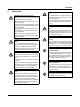
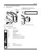
11 Mounting and connection
Mount the module on a 35 mm DIN rail according to
EN60715.
Figure 8 Mounting and removing
Connect the cables to the connection terminal blocks using
a screwdriver.
Figure 9 Connecting the cables for PSR-...-SC
(screw terminal block)
Figure 10 Connecting the cables for PSR-...-SC
(spring-cage terminal block)
12 Startup
Apply the rated control supply voltage (24VDC) at terminal
blocks A1/A2. The PWR LED lights up.
Close sensor circuit S11/S12 and S21/S22. The IN1/2 LED
lights up.
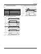
Automatic or manual, monitored start:
Close contacts S11/S34 as follows.
Figure 11 Connection of automatic or manual, monitored
start
1 Automatic start
2 Manual, monitored start with monitored contact exten-
sion
3 Manual, monitored start
When automatic start is selected, the enabling current paths
close.
For manual, monitored start, first press the reset button. The
release of the button causes the enabling current paths to
close.
The K1 and K2 LEDs light up.
If the supply voltage drops or the sensor circuit (S11/S12 or
S21/S22) is opened, the enabling current paths of the output
circuits (13/14, 23/24) open and the contacts enter the safe
state.
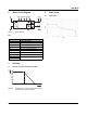
For compliance with UL approval, use copper
wire that is approvedupto 60°C/75°C.
0,5-0,6 Nm
5-7 lb In
7 mm
AWG 24-14
0,2-2,5 mm
2
PSR-...-SC
A
B
A
A
B
8 mm
AWG 24-16
0,2-1,5 mm
2
PSR-...-SP
S21 S34
1
0V
K3
K4
S11 S34
2
24V DC
S11 S34
3
24V DC