
Datasheet


PSR-MC30
106173_en_01 PHOENIX CONTACT 12
14 Diagnostics
The following section describes the LED indicators for gen-
eral states and error messages as well as possible causes
and remedies.
Function test/proof test
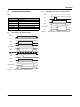
14.1 General states
14.2 Error Messages
Use the function test to check the safety func-
tion. To do this, request the safety function
once by pressing the emergency stop button,
for example. Check whether the safety func-
tion is running correctly by switching the de-
vice on again via the sensor circuits.
PWR
LED
IN1/2
LED
K1
LED
K2
LED
State Notes
ON OFF OFF OFF All relays are not activated. The sensor
circuit is off.
Possible error see error messages
ON ON OFF OFF The sensor circuit is active. Relays K1
and K2 are ready to start and await reset/
start command (S34).
-
ON ON ON ON The sensor circuit is active. All relays are
picked up.
-
PWR
LED
IN1/2
LED
K1
LED
K2
LED
State Possible cause Remedy
ON OFF OFF OFF The sensor circuit is ac-
tively controlled, but no
input LEDs are lit up.
Internal cross-circuit de-
tection is active: potential
cross-circuit in the sensor
circuit.
Switch off the operating volt-
age and rectify the cross-cir-
cuit. Then perform a func-
tion test.
ON ON OFF OFF The sensor circuit is ac-
tive. The reset/start circuit
(S34) is/was activated.
The safety circuit (K1 and
K2) is not picking up.
External error: the read-
back contact (external ac-
tuator) is open in the reset
circuit.
Internal error:
1. The diagnostic contact
is not working correctly.
2. An N/O contact is
welded.
External error: check the ac-
tuator.
Internal error: perform a
power down reset with sub-
sequent function test. If the
error occurs again after
the function test, replace
the device.
ON ON OFF OFF The sensor circuit is ac-
tive. The reset/start circuit
(S34) is/was activated.
The safety circuit (K1 and
K2) is not picking up.
Error during manual reset
S34 (stuck-at at the in-
put).
Remove the error in the
reset/start circuit. Then per-
form a function test.