
Datasheet


PSR-MC34
106174_en_01 PHOENIX CONTACT 7
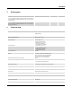
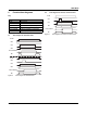
6 Basic circuit diagram
Figure 1 Block diagram
Key:
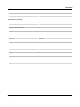
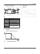
7Derating
7.1 Vertical or horizontal mounting position
Figure 2 Derating curve - vertical or horizontal mounting
position with connected modules
8Load curve
8.1 Ohmic load
Figure 3 Lastkurve Relais - ohmsche Last
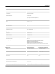
Designation Explanation
A1 +24V power supply
A2 0V power supply
M1 Signal output (PNP)
S11 Output 24V
S12 Input sensor circuit (channel 1)
S22 Input sensor circuit (channel 2)
S34 Start circuit
13/14
Undelayed enabling current paths23/24
23/34
13 23
14 24 34
A1
A2 M1
PWR
24V DC
PSR-MC34
IN 1/2
K1
K2
S34S12S11 S22
10 20 30 40 50 60 70
0
10
20
30
40
50
60
70
80
T [°C]
A
I[A]
TH
²²
27 55
0
72
3