
Datasheet


PSR-MC34
106174_en_01 PHOENIX CONTACT 9
10 Operating and indication elements
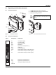
10.1 Connection versions
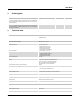
Figure 6 Connection versions
1 COMBICON plug-in screw terminal block
2 COMBICON plug-in spring-cage terminal block
3 Metal lock for fixing to DIN rail
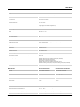
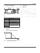
Figure 7 Year of manufacture of the device
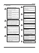
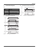
10.2 Connection assignment
0,5-0,6 Nm
5-7 lb In
PSR-...-SC
7 mm
AWG 24-12
0,2-2,5 mm
2
PSR-...-SP
8 mm
AWG 24-16
0,2-1,5 mm
2
P
H
O
E
N
IX
C
O
N
T
ACT
G
m
b
H
&
C
O
.KG
F
la
ch
s
m
a
r
k
ts
tr
a
s
s
e
8
3
2
8
2
5
B
lo
m
b
e
r
g
, G
e
r
m
a
n
y
PSR
-...
O
r
d.-N
o
.: xx xx xxx
Phoenix
Saf
ety Relays
D
o
c
u
m
e
nt
a
tio
n
PSR-...
PWR
P
H
O
E
N
IX
C
O
N
T
ACT
G
m
b
H
&
C
O
.KG
F
la
ch
s
m
a
rk
ts
tr
a
s
s
e
8
3
2
8
2
5
B
lo
m
b
e
r
g
, G
e
r
m
a
n
y
PSR
-...
O
r
d
.-No
.: xx xx xxx
Phoenix
Saf
ety Relays
D
o
c
u
m
e
n
t
a
tio
n
PSR-...
PWR
2
1
3
The year the device was constructed can be
found underneath the CE designation on the
housing.
D
ocu
m
en
ta
tio
n
PSR-...
PWR
14
xxx
e
lays
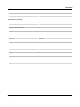
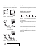
Figure Designation Explanation
A1 +24V power supply
A2 0V power supply
M1 Signal output (PNP)
S34 Start circuit
S12 Input sensor circuit (channel 1)
S11 Output 24V
PWR Power LED (green)
IN1/2 Status indicator sensor circuit; LED (green)
K1 Status indicator safety circuit; LED (green)
K2 Status indicator safety circuit; LED (green)
S21 Input sensor circuit (channel 2)
S22 Input sensor circuit (channel 2)
13/14 Undelayed enabling current paths
23/24/34
A1 A2
M1
S12 S11
S34
S22
34
13
23 24
14
PWR
IN 1/2
K1
K2
PSR-MC34