
Datasheet


PSR-PC20
106255_en_00 PHOENIX CONTACT 9
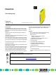
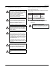
6 Basic circuit diagram
Figure 1 Block diagram
Key:
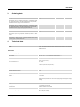
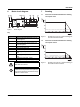
7Derating
7.1 Vertical or horizontal installation for enabling
current path 13/14
Figure 2 Derating curve (13/14) - vertical mounting posi-
tion with connected modules
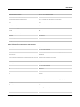
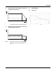
7.2 Vertical or horizontal installation for enabling
current path 13F/14
Figure 3 Derating curve (13F/14) - vertical mounting po-
sition with connected modules
Designation Explanation
A1 +24V control input with active error ac-
knowledgment
A2 0 V (GND)
A1' +24V control input without active error
acknowledgment
M1 Signal output (PNP)
31 +24V diagnostics input
32 Diagnostic output +24V
13F Enabling current path - input with 5AT
fuse
13 Enabling current path - input without 5AT
fuse
14 Enabling current path - output
TBUS Routing of the diagnostic supply voltage
Connect at most 10 devices in series via the
TBUS DIN rail connector.
Confirmation current path 31/32 (N/C contact)
is not an electrically isolated current path and
may only be connected to a maximum voltage
of 26.4V in relation to A2.
M1
A1 A1'
PWR
24V DC
PSR-PC20
ERR
K1
K2
DGN
F2
5A T
F1
5A T
31
32 14
13
13F13F
T-Bus A2
T-Bus
10 20 30 40 50 60 70
10
20
30
40
0
T[°C]
A
I[A]
TH
²²
36
55
9
10 20 30 40 50 60 70
10
20
30
40
0
T[°C]
A
I[A]
TH
²²
55
9
4
65
0