
Datasheet


PSR-PC20
106255_en_00 PHOENIX CONTACT 12
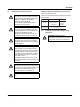
10 Mounting and connection
Mount the module on a 35 mm DIN rail according to
EN60715.
When using the TBUS DIN rail connector to redirect the di-
agnosis power supply, insert it into the DIN rail first.
Figure 9 Mounting and removing
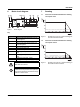
Connect the cables to the connection terminal blocks using
a screwdriver.
Figure 10 Connecting the cables for PSR-...-SC
(screw terminal block)
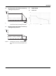
Figure 11 Connecting the cables for PSR-...-SC
(spring-cage terminal block)
11 Startup
Apply the rated control supply voltage to terminals A1/A2
(with active error acknowledgement) or A1'/A2 (without ac-
tive error acknowledgement). The PWR LED lights up.
Enabling current path 13/14 (or 13F/14) closes, and confir-
mation current path 31/32 opens.
In this case, it is vital to observe the mounting
direction of the module and DIN rail connec-
tor:
metal lock at the bottom and connector on the
left.
A
B
C
0,5-0,6 Nm
5-7 lb In
7 mm
AWG 24-14
0,2-2,5 mm
2
PSR-...-SC
A
B
For compliance with UL approval, use copper
wire that is approvedupto 60°C/75°C.
A
A
B
8 mm
AWG 24-16
0,2-1,5 mm
2
PSR-...-SP