
Datasheet


PSR-PC40
106256_en_00 PHOENIX CONTACT 10
9 Operating and indication elements
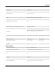
9.1 Connection versions
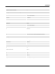
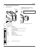
Figure 6 Connection versions
1 COMBICON plug-in screw terminal block
2 COMBICON plug-in spring-cage terminal block
3 Metal lock for fixing to DIN rail
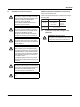
Figure 7 Year of manufacture of the device
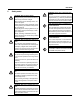
9.2 Connection assignment
0,5-0,6 Nm
5-7 lb In
PSR-...-SC
7 mm
AWG 24-12
0,2-2,5 mm
2
PSR-...-SP
8 mm
AWG 24-16
0,2-1,5 mm
2
P
H
O
E
N
IX
C
O
N
T
ACT
G
m
b
H
&
C
O
.KG
F
la
ch
s
m
a
r
k
ts
tr
a
s
s
e
8
3
2
8
2
5
B
lo
m
b
e
r
g
, G
e
r
m
a
n
y
PSR
-...
O
r
d.-N
o
.: xx xx xxx
Phoenix Safety Relays
D
o
c
u
m
e
nt
a
tio
n
PSR-...
PWR
P
H
O
E
N
IX
C
O
N
T
ACT
G
m
b
H
&
C
O
.KG
F
la
ch
s
m
a
rk
ts
tr
a
s
s
e
8
3
2
8
2
5
B
lo
m
b
e
r
g
, G
e
r
m
a
n
y
PSR
-...
O
r
d
.-No
.: xx xx xxx
Phoenix Safety Relays
D
o
c
u
m
e
n
t
a
tio
n
PSR-...
PWR
2
1
3
The year the device was constructed can be
found underneath the CE designation on the
housing.
D
ocu
m
en
ta
tio
n
PSR-...
PWR
14
xxx
e
lays
Figure Designation Explanation
M1 Signal output (PNP)
A1' +24V control input without active error acknowledgment
Y1 +24V start circuit output
Y2 +24V start circuit input
A1 +24V control input with active error acknowledgment
A2 0 V (GND)
PWR Power LED (yellow)
ERR Error LED (red)
DGN Diagnostics LED (green)
K1/K2 Status indicator safety circuit; LED (green)
13/14 Undelayed enabling current paths
23/24
M1 A1'
Y1
A1 A2
Y2
13
14
23
Y1 Y2
24
PWR
ERR
DGN
PSR-PC40
K
1
/
2