
Datasheet


PSR-PC40
106256_en_00 PHOENIX CONTACT 11
10 Mounting and connection
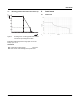
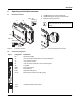
Mount the module on a 35 mm DIN rail according to
EN60715.
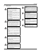
Figure 8 Mounting and removing
Connect the cables to the connection terminal blocks using
a screwdriver.
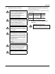
Figure 9 Connecting the cables for PSR-...-SC
(screw terminal block)
Figure 10 Connecting the cables for PSR-...-SC
(spring-cage terminal block)
11 Startup
Apply the rated control supply voltage to terminals A1/A2
(with active error acknowledgement) or A1'/A2 (without ac-
tive error acknowledgement) and connect the Y1/Y2 feed-
back circuit. The PWR LED, the K1/2 LED, and the DGN
LED light up.
Close enabling current paths 13/14 and 23/24.
12 Proof test
In the proof test, you check the individual relay channels.
1. Activate A1/A2 (or A1'/A2).
2. Ensure that the Y1/Y2 feedback circuit is closed.
3. Activate A1/A2 (or A1'/A2).
If the yellow PWR LED, the green K1/2 LED, and the green
DGN LED light up, the module is functional.
The enable contacts are closed.
(Apply 0VDC to signal output M1. Error acknowledgment
via A1 is inactive.)
If the yellow PWR LED and the red ERR LED light up, re-
place the module.
The module-internal locking prevents the enable contacts
from being closed.
(Apply 24VDC to signal output M1. Error acknowledgment
via A1 is inactive.)
For compliance with UL approval, use copper
wire that is approvedupto 60°C/75°C.
0,5-0,6 Nm
5-7 lb In
7 mm
AWG 24-14
0,2-2,5 mm
2
PSR-...-SC
A
B
A
A
B
8 mm
AWG 24-16
0,2-1,5 mm
2
PSR-...-SP
Replace the device in the event of an error.