
Instructions


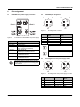

Table Of Contents
- 1 Description
- 2 Table of contents
- 3 Ordering data
- 4 Technical data
- Dimensions (nominal sizes in mm)
- General data
- Connection data
- Interface PROFINET
- PROFINET
- Supply: Module electronics, sensors and actuators (US)
- Supply: Actuators (UA) for additional devices
- Digital inputs
- Digital outputs
- Electrical isolation/isolation of the voltage areas
- Test section
- Mechanical tests
- Conformance with EMC Directive 2014/30/EU
- Approvals
- 5 Internal circuit diagram
- 6 Pin assignment
- 7 Connection example
- 8 Connection notes
- 9 Factory reset via rotary encoding switches
- 10 Local status and diagnostic indicators
- 11 PROFINET IO Device
- 12 Startup
- 13 WBM - Web-based management
- 14 SNMP - Simple Network Management Protocol
- 15 Device description file (GSDML)

AXL E PN DIO16 M12 6M
8443_en_11 PHOENIX CONTACT 8 / 21
5 Internal circuit diagram
Figure 1 Internal wiring of connections
Key:
X31
X32
X01
X02
X03
X04
X05
X06
X07X08
16 16
24 V
3.3 V
µC
U OUT
S
U OUT
A
UIN
S
UIN
A
2
22
2
##
##
2
22
2
##
##
2
22
2
##
##
2
22
2
##
##
X21
X22
ETH1 ETH2
Green area: Network
Blue area: U
S
Yellow area: U
A
Transmitter with electrical isolation
Power supply unit with electrical isolation
Microcontroller
Digital input
Digital output
LED
Transistor
The device and the freely configurable inputs
and outputs are supplied from the voltage U
S
.
The voltage U
A
is only passed through the
device.
Separate switching-off of the outputs is
therefore not possible.
µC