
Instructions
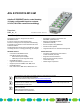
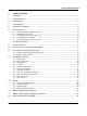
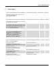

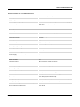


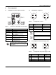

Table Of Contents
- 1 Description
- 2 Table of contents
- 3 Ordering data
- 4 Technical data
- Dimensions (nominal sizes in mm)
- General data
- Connection data
- Interface PROFINET
- PROFINET
- Supply: Module electronics, sensors and actuators (US)
- Supply: Actuators (UA) for additional devices
- Digital inputs
- Digital outputs
- Electrical isolation/isolation of the voltage areas
- Test section
- Mechanical tests
- Conformance with EMC Directive 2014/30/EU
- Approvals
- 5 Internal circuit diagram
- 6 Pin assignment
- 7 Connection example
- 8 Connection notes
- 9 Factory reset via rotary encoding switches
- 10 Local status and diagnostic indicators
- 11 PROFINET IO Device
- 12 Startup
- 13 WBM - Web-based management
- 14 SNMP - Simple Network Management Protocol
- 15 Device description file (GSDML)

AXL E PN DIO16 M12 6M
8443_en_11 PHOENIX CONTACT 9 / 21
6 Pin assignment
6.1 PROFINET and power supply connection
Figure 2 Connections for PROFINET and power supply
6.2 PROFINET pin assignment
Figure 3 Pin assignment, D-coded
6.3 Pin assignment of the power supply U
S
/U
A
Figure 4 Pin assignment of the power supply, T-coded
Designation Meaning
Port 1 (X21) Ethernet port 1
Port 2 (X22) Ethernet port 2
U
S
IN (X31) Power supply IN
(logic, sensors and actuators)
U
A
IN (X31) Power Supply IN
(actuators) for additional devices
U
S
OUT (X32) Power supply OUT
for additional devices
U
A
OUT (X32) Power supply OUT
for additional devices
Ground the device by means of the mounting
screws of the fixing clips or the mounting plate
or the DIN rail.
Port 1 Port 2
Pin Ethernet port 1
(X21)
Ethernet port 2
(X22)
1TX+ TX+
2RX+ RX+
3TX- TX-
4RX- RX-
The shield is connected to FE in the device.
The thread is used for additional shielding.
Pin IN OUT Conductor
colors
1+24 V DC (U
S
) +24 V DC (U
S
)Brown
2GND (U
A
)GND (U
A
)White
3GND (U
S
)GND (U
S
)Blue
4+24 V DC (U
A
) +24 V DC (U
A
)Black
1
2
3
4
X21
2
3
4
1
X22
X32X31
4
3
2
1
4
3
2
1