
Datasheet


TRIO-PS/3AC/24DC/5
103346_en_00 PHOENIX CONTACT 9
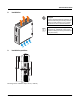
10 Mounting on DIN rails
A B
A
B
Assembly
Position the module with the DIN rail guide on the upper edge
of the DIN rail, and snap it in with a downward motion.
Removing
Pull the snap lever open with the aid of a screwdriver and slide
the module out at the lower edge of the DIN rail.
11 Connection to various systems
+
L1 L2(L3)
−
PE
PE
N
L3
L2
L1
+
L1 L2
(L3)
−
PE
PEN
L3
L2
L1
+
L1 L2(L3)
−
PE
N
L3
L2
L1
+
L1 L2(L3)
−
PE
L3
L2
L1
TN-S TN-C TT iT
The device can be connected to 2- or 3-phase AC networks with nominal voltages 2x/3x 400 V AC ... 500 V AC.
The 2x or 3x 400 V AC ... 500 V AC connection is made using the L1, L2, L3 and PE screw connections.
When connecting the three phases L1, L2 and L3, continuous operation at nominal capacity is ensured without limitations
when one of the phases fails.
ATTENTION: Module can become damaged
In order to comply with the UL certification, use copper cables that are designed for operating temperatures of
>75°C.
In order to comply with EN 60950/UL 60950, flexible cables require ferrules. To safely connect a device, the
ferrules should have a length of at least 10 mm. To achieve a reliable and shockproof connection, strip the
connecting ends according to section "Structure".