
Instructions
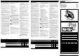


ENGLISH DEUTSCH
23
4
56 8
1
1
40
6
7
10
2
3
4
20
100
200
60
30
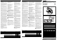
Überstromfaktor/Overload current factor
(Das Verhältnis zwischen dem tatsächlichen Strom und dem parametrierten Nennstrom/
The ratio between the actual current and the parameterized rated current)
Auslösezeit/Release Time [s]
Max.
Min.
[1] Class 10A
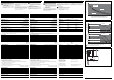
Abb./Fig. 5
Auslösekennlinie bei 20 °C [1]
Tripping characteristics for 20 °C [1]
10 20 30 40 50 70
0
60
6
8
0,1
4
2
9
7
5
3
1
10 20 30 40 50
70
0
60
ELR...-24DC/...
ELR...-230AC/...
6
8
0,1
4
2
9
7
5
3
1
0,6
0,6
Umgebungstemperatur/Ambient temperature [°C]
Laststrom/Load current 9 A:
Laststrom/Load current 0,6 A:
Laststrom/Load current 2,4 A:
Laststrom/Load current 9 A:
Laststrom/Load current 0,6 A:
Laststrom/Load current 2,4 A:
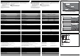
Abb./Fig. 6
Laststrom/
Load current [A]
= angereit mit Abstand von 20 mm/in rows with spacing of 20 mm
= angereit ohne Abstand/in rows with zero spacing
Laststrom/
Load current [A]
Deratingkurven bei 100% Einschaltdauer (Weitere Daten auf Anfrage)
Derating curves for 100% operating time (more data available on request)
5. Applikationsbeispiele
Ein Abschalten der Steuerspeisespannung
bei angesteuertem Motor ist immer mit
Verschleiß im Hybrid-Motorstarter verbun-
den!
Diese Schaltung sollte daher nur angewendet
werden, wenn über die gesamte Systemle-
bensdauer mit nicht mehr als 10.000 Abschal-
tungen gerechnet werden muss.
5.1. Motorschutz
Alle für die Sicherheit relevanten Funktionen werden
ohne äußeren Einfluss durch der Hybrid-Motorstar-
ter realisiert. Besondere Schaltungstechniken sind
nicht notwendig (Abb.7).
5.2. Motor mit Bremse
Wird ein Motor mit Bremse (Anschluss im Mo-
torklemmbrett) angeschlossen, muss die Bremse an
den Anschlüssen 2/T1 und 6/T3 (400 V AC) ange-
bunden werden. Eine 230 V AC-Bremse ist an den
Anschluss 4/T2 und den Sternpunkt des Motors an-
zuschließen.
Beachten Sie bitte:
Die Motorstromüberwachung muss um den
Wert der Bremse (Nennstrom Bremse) erhöht
werden. Stellen Sie dieses entsprechend am
Hybrid-Motorstarter ein (siehe Punkt 4.3,
Abb.4)!
5.3. Anschluss von Hilfsrelais
Hilfsrelais (z.B. PLC RSC 230UC/21, Art.-Nr.:
2966207) zum Ansteuern von externen Bremsen
oder Rückmeldungen z.B. an die SPS müssen an
den Anschluss „4T2“ und „N“ der Anlage ange-
schlossen werden.
U
1
V
1
W
1
P
E
M
3
F
1
L1
L2
L3
N
PE
24
V
D
C
G
N
D
9
7
2
/
T
1
4
/
T
2
6
/
T
3
O
N
1
/
L
1
3
/
L
2
5
/
L
3
ELR H3-I-.../500AC-...
9
6
/9
8
9
5
R
E
S
M
A
N
A
U
T
U
S
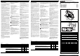
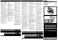
Abb./Fig. 7
Schaltbeispiele / Example circuits
5. Application examples
Switching off the control voltage supply
with a controlled motor always results in
wear in the hybrid motor starter.
This switch should only be used if no more
than 10,000 shutdowns can be expected over
the entire lifespan system.
5.1. Motor overload protection
All safety-relevant functions are implemented with-
out external influences by the hybrid motor starter.
Special wiring techniques are not required (fig. 7).
5.2. Motor with brake
If a motor with brake is connected (in the motor ter-
minal board), the brake must be connected with con-
nections 2/T1 and 6/T3 (400 V AC). A 230 V AC
brake must be connected with 4/T2 and the neutral
point of the motor.
Please note that:
The motor current monitoring must be increa-
sed by the brake value (nominal value of the
brake).
This has to be set at the hybrid motor starter
(see point 4.3, fig.4)!
5.3. Auxiliary relay connection
Auxiliary relays (e.g. PLC RSC 230UC/21, Order
No.: 2966207) for activating external brakes or feed-
back to e.g. the PLC must be connected to the “4T2”
and “N” connection of the system.
Technical Data Technische Daten
Input data Eingangsdaten ELR H3-I-24DC/... ELR H3-I-230AC/...
Rated control supply voltage U
s
in acc. with IEC 60947-1/UL 508 Bemessungssteuerspeisespannung U
s
nach IEC 60947-1/UL 508 24 V DC 230 V AC (50/60 Hz)
Control supply voltage range Steuerspeisespannungsbereich 19,2…30 V DC (32 V DC, max. 1 min.) 85…253 V AC
Rated control supply current in acc. with IEC 60947-1 Bemessungssteuerspeisestrom nach IEC 60947-1 ≤ 40 mA ≤ 4 mA
Control input ON: Switching level “Low” Steuereingang ON: Schaltpegel „Low“ -3…9,6 V DC < 44 V AC
Switching level “High” Schaltpegel „High“ 19,2…30 V DC 85…253 V AC
Input current Eingangsstrom ≤ 5 mA ≤ 7 mA
Output data Load side Ausgangsdaten Lastseite ELR H3-I-...-0,6 ELR H3-I-...-2 ELR H3-I-...-9
Switching principle Schaltungsprinzip Endstufe mit Bypass, dreiphasige galvanisch getrennte Abschaltung /
Output stage with bypass, three-phase electrically isolated shutdown
Rated operating voltage U
e
in acc. with IEC 60947-1 Bemessungsbetriebsspannung U
e
nach IEC 60947-1 500 V AC (50/60 Hz)
Operating voltage range in acc. with IEC 60947-1 / in acc. with UL 508 Betriebsspannungsbereich nach IEC 60947-1 / nach UL 508 42…550 V AC / 42…500 V AC
Load current at 20 °C (see derating curve, fig. 6) Laststrom bei 20 °C (siehe Deratingkurve, Abb. 6) 0…0,6 A 0…2,4 A 0…9,0 A
Rated operating current I
e
in acc. with IEC 60947-1
AC-51 in acc. with IEC 60947-4-3
AC-53a in acc. with IEC 60947-4-2/
in acc. with UL 508
Bemessungsbetriebsstrom I
e
nach IEC 60947-1
AC-51 nach IEC 60947-4-3
AC-53a nach IEC 60947-4-2/
nach UL 508
0,6 A
0,6 A
0,6 A
2,4 A
2,4 A
2,4 A
9 A
6,5 A
6,5 A
Nominal switching capacity Full load (power factor = 0.4)
Full load (power factor = 0.8)
Nennschaltleistung Full Load (power factor = 0,4)
Full Load (power factor = 0,8)
0,3 kW (0,4 HP)
0,5 kW (0,6 HP)
0,9 kW (1,2 HP)
1,7 kW (2,2 HP)
2,3 kW (3,0 HP)
4,6 kW (6,1 HP)
Leakage current (input, output) Leckstrom (Eingang, Ausgang) 0 mA 0 mA 0 mA
Residual voltage at I
e
Restspannung bei I
e
< 200 mV < 300 mV < 300 mV
Surge current Stoßstrom 100 A (t = 10 ms)
Input protective circuit Varistors Eingangsschutzbeschaltung Varistoren
Short circuit current rating SCCR acc. to UL 508
- suitable for use on a circuit capable of delivering not more than 5 kA
rms
symmetrical amperes, 500 V maximum
- suitable for use on a circuit capable of delivering not more than 100 kA
rms
symmetrical amperes,
500 V maximum when protected by a 30 A class J or CC fuse
Short circuit current rating SCCR nach UL 508
- geeignet für den Einsatz in Stromkreisen, die nicht mehr als 5 kA
eff
symmetrischen Strom liefern, max. 500 V
- geeignet für den Einsatz in Stromkreisen, die nicht mehr als 100 kA
eff
symmetrischen Strom liefern,
max. 500 V, wenn durch eine 30 A-Sicherung Klasse J oder CC abgesichert wird
Reply output Rückmeldeausgang
Contact type Single contact, 1 PDT contact Kontaktausführung Einfachkontakt, 1 Wechsler
Contact material Ag alloy, hard gold-plated Kontaktmaterial Ag-Legierung, hartvergoldet
When used as bei Verwendung als Signalkontakt / Signal contact Leistungskontakt / Power contact
Max. switching voltage Max. Schaltspannung 30 V AC/36 V DC 250 AC/DC
Min. switching voltage Min. Schaltspannung 100 mV 12 V AC/DC
Limiting continuous current Grenzdauerstrom 50 mA 6 A
Min. switching current Min. Schaltstrom 1 mA 10 mA
Max. interrupting rating, ohmic load 24 V DC
48 V DC
60 V DC
110 V DC
220 V DC
250 V AC
Max. Abschaltleistung, ohmsche Last 24 V DC
48 V DC
60 V DC
110 V DC
220 V DC
250 V AC
1,2 W
-
-
-
-
-
140 W
20 W
18 W
23 W
40 W
1500 VA
Measurement technology (in reference to the trigger characteristic, fig. 5) Messtechnik (bezogen auf Auslösekennlinie, Abb. 5) ELR H3-I-...-0,6 ELR H3-I-...-2 ELR H3-I-...-9
Current measurement Strommessung
Range Bereich 0,075…0,6 A 0,18…2,4 A 1,5…9,0 A
Symmetry monitoring Symmetrieüberwachung
Amount I
max
> I
nom
=> (I
max
- I
min
/ I
max
) Betrag I
max
> I
nenn
=> (I
max
- I
min
/ I
max
) ≥ 33 % / ≥ 67 % ≥ 33 % / ≥ ≥ 33 % / ≥ 67 %
Amount I
max
< I
nom
=> (I
max
- I
min
/ I
nom
) Betrag I
max
< I
nenn
=> (I
max
- I
min
/ I
nenn
) ≥ 33 % / ≥ 67 % ≥ 33 % / ≥ 67 % ≥ 33 % / ≥ 67 %
Response time Ansprechzeit 2 min./1,8 s 2 min./1,8 s 2 min./1,8 s
Blocking protection Blockierschutz
I(L1) or I(L3) I(L1) oder I(L3) --> 45 A
Response time Ansprechzeit --2 s
Trigger characteristic (see fig. 5) in acc. with IEC 60947 Auslösekennlinie (s. Abb. 5) nach IEC 60947 - - Class 10A
Cooling time Abkühlzeit --20 min.
General data Allgemeine Daten ELR H3-I-...-0,6 ELR H3-I-...-2 ELR H3-I-...-9
Power dissipation min./max. Verlustleistung min./max. 0,88 W/2,5 W 0,88 W/4,1 W 0,88 W/7 W
Max. switching frequency Max. Schaltfrequenz 2 Hz
Service life cycles Lebensdauer Schaltspiele 3 x 10
7
Degree of protection Schutzart IP20
Ambient temperature range Operation
Transport/storage
Umgebungstemperaturbereich Betrieb
Transport, Lagerung
-25 °C…+70 °C
-40 °C…+80 °C
Rated surge voltage Bemessungsstoßspannung 6 kV (ELR H3-I-24DC/...) 4 kV (ELR H3-I-230AC/...)
- between control input, control supply and switching voltage - zwischen Steuereingangs-, Steuerspeise- und Schaltspannung
• Nominal mains voltage (≤ 500 V AC) • Netznennspannung (≤ 500 V AC) Safe isolation (EN 50178) Basic insulation (IEC 60947-1)
• Nominal mains voltage (≤ 300 V AC, e.g. 230/400 V AC, 277/480 V AC) • Netznennspannung (≤ 300 V AC, z.B. 230/400 V AC, 277/480 V AC) Safe isolation (IEC 60947-1) -
• Nominal mains voltage (300…500 V AC) • Netznennspannung (300…500 V AC) Basic insulation (IEC 60947-1) -
- between control input, control supply voltage and reply output - zwischen Steuereingangs-, Steuerspeisespannung und Rückmeldeausgang Safe isolation (IEC 60947-1) Safe isolation (IEC 60947-1)
- between reply output and switching voltage - zwischen Rückmeldeausgang und Schaltspannung
• Nominal mains voltage (≤ 500 V AC) • Netznennspannung (≤ 500 V AC) Safe isolation (EN 50178) -
• Nominal mains voltage (≤ 300 V AC, e.g. 230/400 V AC, 277/480 V AC) • Netznennspannung (≤ 300 V AC, z.B. 230/400 V AC, 277/480 V AC) Safe isolation (IEC 60947-1) Safe isolation (IEC 60947-1, EN 50178)
• Nominal mains voltage (300…500 V AC) • Netznennspannung (300…500 V AC) Basic insulation (IEC 60947-1) Basic insulation (IEC 60947-1)
Sichere Trennung = safe isolation
Basisisolierung = basic isolation
Surge voltage category Überspannungskategorie III
Pollution degree Verschmutzungsgrad 2
Standards/regulations
Power station requirement
Normen/Bestimmungen
Kraftwerksanforderung
IEC 60947-4-2
DWR 1300/ZXX01/DD/7080.8d
Coordination type Zuordnungsart 1
Mounting position vertical (horizontal DIN rail) Einbaulage senkrecht (Tragschiene waagerecht)
Mounting (see derating curve, fig. 6) can be aligned with ≥ 20 mm spacing Montage (s. Abb.6: Deratingkurven) anreihbar mit Abstand 20 mm
Housing: Material / Dimensions (W/H/D) Gehäuse: Material / Abmessungen (B / H / T) PA 66 / (22,5 / 99 / 114,5) mm
Connection data (conductor cross-section) Screw terminal block (solid/stranded)
– See connection notes! – M3 thread, recommended torque
Anschlussdaten (Leiterquerschnitt) Schraubklemmen (starr/flexibel)
– Siehe Anschlusshinweise! – Gewinde M3, empfohlenes Anzugsmoment
0,14–2,5 mm
2
(AWG 26–14)
0,5–0,6 Nm/5–7 lbs-ins
Weight approx. Gewicht ca. 212 g
Conformance / Approvals acc. to UL 508 Konformität / Zulassungen nach UL 508 NLDX File: E228652
NMFT File: E323771