EMpro - multi-functional energy measuring devices for front panel installation User manual
User manual EMpro - multi-functional energy measuring devices for front panel installation 2020-03-05 UM EN EMpro front panel, Revision 00 This user manual is valid for: Order No. 2907945 2908286 2907944 2908285 2907946 2908301 2907953 2908302 108904_en_00 Designation EEM-MA770 EEM-MA771 EEM-MA770-R EEM-MA771-R EEM-MA770-PN EEM-MA771-PN EEM-MA770-EIP EEM-MA771-EIP PHOENIX CONTACT GmbH & Co. KG • Flachsmarktstraße 8 • 32825 Blomberg • Germany phoenixcontact.
Table of contents Table of contents 1 2 For your safety ...........................................................................................................................7 1.1 Identification of warning notes ...............................................................................7 1.2 Qualification of users .............................................................................................7 1.3 Field of application of the product ............................................
EMpro - multi-functional energy measuring devices for front panel installation 5.2 6 7 8 Basic device configuration via the web server .....................................................37 5.2.1 Step 1: Network settings ......................................................................38 5.2.2 Step 2: Selecting the grid type .............................................................39 5.2.3 Step 3: Configuration of the current input (current transformer) ...........40 5.2.
Table of contents 8.2 9 Transferring configuration data ............................................................................75 8.2.1 Exporting configuration data ................................................................75 8.2.2 Importing configuration data .................................................................76 8.2.3 Direct transfer of configuration data .....................................................77 Measuring technology ................................................
EMpro - multi-functional energy measuring devices for front panel installation 11.2 Modbus .............................................................................................................135 11.2.1 Function .............................................................................................135 11.2.2 Modbus/RTU ......................................................................................136 11.2.3 Modbus/TCP ....................................................................
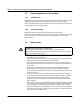
For your safety 1 For your safety Read this user manual carefully and keep it for future reference. 1.1 Identification of warning notes This symbol indicates hazards that could lead to personal injury. There are three signal words indicating the severity of a potential injury. DANGER Indicates a hazard with a high risk level. If this hazardous situation is not avoided, it will result in death or serious injury. WARNING Indicates a hazard with a medium risk level.
EMpro - multi-functional energy measuring devices for front panel installation 1.3 1.3.1 Field of application of the product Intended use The EMpro energy measuring devices described in this user manual are suitable for installation in electrical systems with different voltage levels and performance classes. Keep in mind that electrical systems pose hazards due to high voltages, high short-circuit currents, electric arcs and/or other hazards. 1.3.
For your safety – – 108904_en_00 Check that the measuring device is working correctly by measuring a known voltage and a known current. Ground each current transformer on the secondary side.
EMpro - multi-functional energy measuring devices for front panel installation 10 / 192 PHOENIX CONTACT 108904_en_00
Device description 2 Device description The EMpro energy measuring devices (EEM-MA77x types) are universally deployable, high-precision, network-compatible measuring devices with LC display, which can measure, evaluate and process voltages and currents in one, two and three-phase power supply systems. For voltage measurements, up to four inputs are available; for current measurements, up to three inputs are available. You can use EMpro energy measuring devices in TN and IT systems.
EMpro - multi-functional energy measuring devices for front panel installation Numerous parameters that are important for operating an electrical system are determined by means of the voltages and currents measured by the EMpro energy measuring devices. Apparent power, active power and reactive power are measured in all four quadrants (consumption, supply). EMpro energy measuring devices have an integrated web server.
Device description Other features of the EMpro energy measuring devices are: – Firmware update function – Password protection (local and web-based management (WBM)) – Deactivation of control buttons for configuration – Sealable connection fields – Export, import and direct transfer of configuration data – Color changes on display (white, red) in the event of errors/events The following measurement values/parameters are shown on the LC displays of EMpro energy measuring devices: – Voltage U [V] (L-L, L-N) –
EMpro - multi-functional energy measuring devices for front panel installation A variety of parameters from the EMpro energy measuring device can be read or configured in order to communicate with higher-level control systems. These parameters, the associated addresses, additional information and help texts are available on the web server. All information required for setting up communication with higher-level control systems is contained in a register table on the integrated web server.
Device description 2.
EMpro - multi-functional energy measuring devices for front panel installation 16 / 192 PHOENIX CONTACT 108904_en_00
Mounting and installation 3 Mounting and installation 3.1 Mounting You can install the device in a front panel or control cabinet door. 5 B A Figure 3-1 Mounting B A B Figure 3-2 A Mounting terminal covers To ensure a firm and tight fit of the device in accordance with IEC 60529/EN 60529, proceed as follows during mounting: 1. Stretch the seal over the rear of the device and position it against the inside of the display. 2. Push the device into the mounting opening from the front.
EMpro - multi-functional energy measuring devices for front panel installation 3.2 Installation DANGER: Risk of electric shock If the device is disconnected, the secondary side of the relevant current transformers must be short circuited. Install the current sensors and corresponding measuring devices only when the power supply of the system is disconnected. When the current transformer is operated with an open secondary circuit, hazardous voltages may occur at the secondary terminal blocks.
Mounting and installation 3.2.1 Pin assignment 3.2.1.1 Current transformer Maximum tightening torque for the relevant screws: 0.5 Nm ... 0.6 Nm.
EMpro - multi-functional energy measuring devices for front panel installation 3.2.1.
Mounting and installation 3.2.2 Supply You can connect the device supply as follows: 1. Connection (L/N) 2. Connection (L/L) Connection L/N L N(L) L1´ L2´ L3´ N´ PE´ L1 L2 L3 N PE Figure 3-5 Connection L/N Connection L/L L L L1´ L2´ L3´ N´ PE´ L1 L2 L3 N PE Figure 3-6 Connection L/L Supply voltage range: 100 V AC ... 400 V AC ±20% 150 V DC ...
EMpro - multi-functional energy measuring devices for front panel installation 3.2.3 Grid types The device is designed for connection to various network types in two-, three- or four-conductor networks with symmetrical or asymmetrical load. Where current sensors are concerned, a differentiation is made between current transformers and Rogowski coils, depending on the device type.
Mounting and installation 3PH-3W-1CT V1 V2 V3 VN 6 I1 I2 I3 S1 S2 S1 S2 S1 S2 L1 L2 L3 N PE L1´ L2´ L3´ N´ PE´ Figure 3-9 Three-phase network, three conductors, one current transformer 3PH-3W-2CT V1 V2 V3 VN 6 I1 I2 I3 S1 S2 S1 S2 S1 S2 L1 L2 L3 L1´ L2´ L3´ PE PE´ Figure 3-10 Three-phase network, three conductors, two current transformers 3PH-3W-3CT V1 V2 V3 VN 6 I1 I2 I3 S1 S2 S1 S2 S1 S2 L1 L2 L3 N PE L1´ L2´ L3´ N´ PE´ Figure 3-11 Three-phase network, three conductors, three current
EMpro - multi-functional energy measuring devices for front panel installation 3PH-4W-3CT V1 V2 V3 VN 6 I1 I2 I3 S1 S2 S1 S2 S1 S2 L1 L2 L3 N PE L1´ L2´ L3´ N´ PE´ Figure 3-13 Three-phase network, four conductors, three current transformers 2PH-3W-2CT V1 V2 V3 VN L1 L2 L3 N PE Figure 3-14 24 / 192 PHOENIX CONTACT 6 I1 I2 I3 S1 S2 S1 S2 S1 S2 L1´ L2´ L3´ N´ PE´ Two-phase network, three conductors, two current transformers 108904_en_00
Mounting and installation 3.2.3.
EMpro - multi-functional energy measuring devices for front panel installation 3PH-4W-1RC V1 V2 V3 VN 6 RC1 RC2 RC3 W1 B1 W2 B2 W3 B3 L1 L2 L3 N PE L1´ L2´ L3´ N´ PE´ Figure 3-19 Three-phase network, four conductors, one Rogowski coil 3PH-4W-3RC V1 V2 V3 VN 6 RC1 RC2 RC3 W1 B1 W2 B2 W3 B3 L1 L2 L3 N PE L1´ L2´ L3´ N´ PE´ Figure 3-20 Three-phase network, four conductors, three Rogowski coils 2PH-3W-2RC V1 V2 V3 VN L1 L2 L3 N PE Figure 3-21 26 / 192 PHOENIX CONTACT 6 RC1 RC2 RC3 W1 B1 W2 B
Operating and indication elements 4 Operating and indication elements EMpro 1 400,00 V U23 400,00 V U31 400,00 V U12 23456 1 1 2 3 2 3 4 2 3 LCD display, two-color backlit Pulse LED Operating buttons 1...4 for displaying measured values and for changing the configuration 4.1 Technical data of the display Technical data 108904_en_00 Display technology FSTN positive, transflective Resolution of devices for installation on front panel 170 x 128 Viewing angle Min.
EMpro - multi-functional energy measuring devices for front panel installation 4.
Operating and indication elements 4.3 Table 4-2 Icon Operating elements on the display (softkeys) Meaning of the softkeys Meaning Open/close settings menu Scroll up Scroll down Select menu page Exit menu page Edit setting Apply modified setting Increment (increase) Decrement (decrease) Next position Confirm query Reject query/first configuration: go back to start Reset: The displayed values are reset.
EMpro - multi-functional energy measuring devices for front panel installation 30 / 192 PHOENIX CONTACT 108904_en_00
Basic device configuration 5 Basic device configuration The first time the energy measuring device is switched on, the installation wizard for the first configuration (basic device configuration) automatically starts. In the basic device configuration, you can edit the default settings of the device. Depending on the requirements, you can perform the basic device configuration via the display or via the integrated web server.
EMpro - multi-functional energy measuring devices for front panel installation 5.1.2 Figure 5-3 1. 2. Figure 5-4 32 / 192 PHOENIX CONTACT Network settings If you do not want to edit the network settings, press the button. If you want to edit the network settings, press the button. 5.1.3 1. 2. 3. 4. 5. Step 2: Network settings Step 3: IPv4 IPv4 To enter a network setting, use the or button to scroll to the desired setting. To open edit mode, press the button.
Basic device configuration 5.1.4 Step 4: Grid type Current transformer Figure 5-5 Selection of grid type with current transformers Rogowski coil Figure 5-6 1. 2. Selection of grid type with Rogowski coils Use the or button to select the desired grid type. To proceed, press the button. Explanations and information on the various grid types are available in Section “Grid types” on page 22.
EMpro - multi-functional energy measuring devices for front panel installation 5.1.5 Figure 5-7 1. 2. 3. Step 5a: Current input (energy measuring device with current transformer) Current input (energy measuring device with current transformer) To open the edit mode for the “Primary” device setting, press the To set the primary current, press the buttons and . To apply the change, press the button. button. To set the secondary current, proceed in the same way as for setting the primary current. 4. 5.
Basic device configuration 5.1.6 Figure 5-8 1. 2. 3. Step 5b: Current input (energy measuring device with Rogowski coil) Current input (energy measuring device with Rogowski coil) Use the button to open the edit mode of the “Manufacturer” device setting. To make changes, use the buttons and . To apply the change, press the button. The same procedure applies to editing the nominal current. 4. 5. To activate or deactivate a checkbox, press the button.
EMpro - multi-functional energy measuring devices for front panel installation 5.1.8 Figure 5-10 1. 2. 3. Figure 5-11 2. 36 / 192 PHOENIX CONTACT Configuration conclusion Use the buttons and to check your configured settings. If you are satisfied with the first configuration, finish it by pressing the To restart the first configuration, press the button. 5.1.9 1. Step 7: Configuration overview button.
Basic device configuration 5.1.10 Step 9: Activating the PIN Figure 5-12 1. 2. 3. 4. Activating the PIN To activate the PIN, press the button. Use the buttons and to enter the desired PIN. To apply the changes, press the button. To finish the basic device configuration, press the button. To ensure safe operation, we recommend changing the access data for the display! For additional information, please refer to Section “Configuration” on page 69. 5.
EMpro - multi-functional energy measuring devices for front panel installation 5.2.1 Step 1: Network settings The first step in the basic device configuration is the network settings. Navigation on the web server “Network settings” Figure 5-13 Network settings Status Here, an overview of the current network configuration is displayed. Settings Enter the desired network settings as appropriate for the respective application.
Basic device configuration 5.2.2 Step 2: Selecting the grid type The second step is the selection of the grid type for the application. Figure 5-14 Grid type Taking the device installation into account, select the desired grid type from the options provided in the overview.
EMpro - multi-functional energy measuring devices for front panel installation 5.2.3 Step 3: Configuration of the current input (current transformer) Depending on the device selection and the associated device-specific current sensors, the current input setting may vary. Configuring the current input is the third step of the basic device configuration. Figure 5-15 Current input, current transformer Primary Enter the primary current of the application here.
Basic device configuration 5.2.4 Step 3: Configuration of the current input (Rogowski coil) Depending on the device selection and the associated device-specific current sensors, the current input setting may vary. Configuring the current input is the third step of the basic device configuration. Figure 5-16 Current input (Rogowski coil) Primary Enter the primary current of the application here. Preselection Select a Rogowski coil from Phoenix Contact.
EMpro - multi-functional energy measuring devices for front panel installation Invert I1 With this function, the respective phase of the Rogowski coil is inverted by the firmware. It is no longer necessary to rewire the two conductors. If you use Rogowski coils from manufacturers other than Phoenix Contact, you have to configure additional settings. Transmission factor Enter the amplitude transmission factor (mV/kA) of the Rogowski coil.
Basic device configuration 5.2.5 Step 4: Voltage input If you use a voltage transducer in your application, activate the checkbox here. Subsequently follow the next steps.
EMpro - multi-functional energy measuring devices for front panel installation 5.2.6 Figure 5-18 Optional: Voltage transducer Voltage input with voltage transducer Primary Enter the primary voltage of the voltage transducer. Secondary Enter the secondary voltage of the voltage transducer.
Basic device configuration 5.2.7 Figure 5-19 Step 5: Configuration overview Configuration overview Check all settings and close the basic device configuration.
EMpro - multi-functional energy measuring devices for front panel installation 46 / 192 PHOENIX CONTACT 108904_en_00
Navigation structure and display 6 Navigation structure and display 6.
EMpro - multi-functional energy measuring devices for front panel installation 6.
Navigation structure and display The figure shows the start screen of the web server in operating mode after the basic device configuration has been completed.
EMpro - multi-functional energy measuring devices for front panel installation 50 / 192 PHOENIX CONTACT 108904_en_00
Device settings and information 7 Device settings and information 7.1 Selecting the language The languages for the display and the web server can differ. Thus, changing the language via the display does not affect the language set in the web server, and vice versa. Navigation on the display “Language” Figure 7-1 “Language” menu Figure 7-2 Language selection You can select the display language via the display. The default setting for the language is English.
EMpro - multi-functional energy measuring devices for front panel installation 7.2 Date and time When the device is switched off, or in the event of a power loss, the device retains the system time for at least one day. This is usually adequate for maintenance and installation work. 7.2.1 Navigation on the display Reading the date and time “Date / Time” Figure 7-3 “Date / Time” menu Figure 7-4 Settings: “Date / Time” On the device display, you can only read the date and time settings.
Device settings and information 7.2.2 Navigation on the web server Setting the date and time manually “Settings, Date / Time, Settings, Manually” mode Figure 7-5 “Settings, Date / Time, Settings, Manually” mode Status Here, the current date and current time are shown. Settings Here, you can change the settings for the date and time. Time zone Here, you can select a time zone. You can find a list of all time zones in Section “Time zones” on page 55.
EMpro - multi-functional energy measuring devices for front panel installation 7.2.3 Navigation on the web server Synchronizing the date and time with an SNTP server “Settings, Date / Time, Settings, SNTP Server” mode Figure 7-6 Menu: “Settings, Date / Time, Settings, SNTP Server” mode Settings Here, you can change the settings for the date and time. Mode Via the “SNTP server” Modbus, the internal clock of the device is automatically synchronized with an SNTP server (Simple Network Time Protocol).
Device settings and information 7.2.
EMpro - multi-functional energy measuring devices for front panel installation GMT +08:00 Asia (Brunei, Hong Kong, Kuala Lumpur, Singapore, Taipei, Manila), Australia (Perth, West) GMT +08:45 Australia (Eucla) GMT +09:00 Asia (Irkutsk, Seoul, Tokyo) GMT +09:30 Australia (Adelaide, Darwin, North, South) GMT +10:00 Asia (Yakutsk) Australia (Brisbane, Melbourne, Queensland, Sydney, Tasmania) GMT +11:00 Asia (Vladivostok) GMT +11:30 Pacific (Norfolk) GMT +12:00 Asia (Kamchatka) Pacific (Guadalc
Device settings and information 7.2.5 Navigation on the web server Summer time rule “Settings, Date / Time, Settings, Summer time rule” Figure 7-7 Menu: “Settings, Date / Time, Settings, Summer time rule” Status Here, the current date and current time are shown. Settings Here, you can change the settings for the date and time. You can select the summer time rule for Europe or the USA, or set a summer time rule manually.
EMpro - multi-functional energy measuring devices for front panel installation 7.3 7.3.1 Navigation on the display Adjusting the display (contrast, brightness, illumination time of backlight) Adjusting the contrast of the display “Display, Contrast” Contrast Figure 7-8 Menu: “Display, Contrast” Figure 7-9 Settings: “Display, Contrast” You can set the contrast of the display. The default setting for the contrast is 50%.
Device settings and information 7.3.2 Navigation on the display Adjusting the brightness of the display “Display, Brightness“ Figure 7-10 Menu: “Display, Brightness“ Figure 7-11 Settings: “Display, Brightness“ You can adjust the brightness of the display. The default setting for the brightness of the display is 100%.
EMpro - multi-functional energy measuring devices for front panel installation 7.3.
Device settings and information Permanent light When the “Permanent light” checkbox is enabled, the white backlight of the display is on permanently. Figure 7-14 Settings: “Illumination time” Permanent light When the “Permanent light” checkbox is disabled, the white backlight of the display is off. Illumination duration When the “Permanent light” checkbox is disabled, you can freely define the duration for which the backlight remains lit. The default setting for the illumination time is 20 seconds.
EMpro - multi-functional energy measuring devices for front panel installation 7.3.4 Navigation on the display Standard display Selecting the format of the standard display (IEC or IEEE) “Display, Standard display” Figure 7-15 Menu: “Display, Standard display” Figure 7-16 Settings: “Display, Standard display” You can choose between the formats IEC and IEEE for displaying the measured values and the associated units. The default setting is IEC.
Device settings and information 7.3.5 Navigation on the display Alarm light Activating color change for alarm “Display, Alarm light” Figure 7-17 Menu: “Display, Alarm light” Figure 7-18 Settings: “Display, Alarm light” The backlight of the display can change from white to red in the event of an error (color change). When the “Alarm light” checkbox is enabled, the color change is active. In the default setting, the color change is enabled.
EMpro - multi-functional energy measuring devices for front panel installation 7.3.6 Navigation on the display Refresh time Selecting the refresh time for displaying measured values “Display, Refresh time” Figure 7-19 Menu: “Display, Refresh time” Figure 7-20 Settings: “Display, Refresh time” You can choose between three refresh times for displaying the measured values: – 500 ms – 1s – 2s The default setting for the refresh time is 1 s.
Device settings and information 7.3.7 Navigation on the web server Adjusting the display via the web server “Settings, Display” Figure 7-21 Web server: “Settings, Display” Status Here, the current settings for the display are shown. It is also possible to modify them here. Standard display Here, you can choose between the formats “IEC” or “IEEE”. Activate configuration via display If this checkbox has been enabled, you can configure the device via the display.
EMpro - multi-functional energy measuring devices for front panel installation 7.
Device settings and information – Bootloader revision 7.5 Navigation on the display Resetting the device to default settings “System, Factory reset” Figure 7-24 Menu: “System, Factory reset” Figure 7-25 Menu: “System, Factory reset” With the device PIN, the device can be reset to the default settings. In the process, all configurations are lost and the device is returned to the delivery state.
EMpro - multi-functional energy measuring devices for front panel installation 68 / 192 PHOENIX CONTACT 108904_en_00
Configuration 8 Configuration The device configuration is set by default as follows. Configuration via the display You can use the control buttons on the front of the device to enter the basic device configuration and configure settings on the display. Configuration via web server The web server is the tool provided for device configuration.
EMpro - multi-functional energy measuring devices for front panel installation 8.1 Access and passwords For your own safety, change the access data. 8.1.1 Navigation on the display Editing access data via the display “System, PIN xxxx” Figure 8-1 Menu: “System, PIN xxxx” Figure 8-2 Settings: “System, PIN xxxx” The default setting for the PIN is “0100”. 1. 2. Under “PIN”, change the preset PIN for access permission. Subsequently apply it by confirming the change.
Configuration 8.1.2 Navigation on the web server Editing access data via the web server “System, User management, Change password” Figure 8-3 Menu: “System, User management, Change password” The default setting for the password is “adm1n”. 1. 2. 108904_en_00 Under “Change password”, change the preset password for access permission. Confirm the change by clicking the “Change password” button.
EMpro - multi-functional energy measuring devices for front panel installation 8.1.3 Navigation on the web server Deactivating the configuration via the display “Settings, Display” Figure 8-4 Menu: “Settings, Display” The device provides an option for protection against manipulative access: You can prevent access to the device and thus changes to the configured data by disabling the “Activate configuration via display” checkbox.
Configuration 8.1.4 Deactivating the Modbus communication interface You can prevent device access via the Modbus communication interface by deactivating the communication interface (“WBM active”).
EMpro - multi-functional energy measuring devices for front panel installation If you disable the “WBM active” checkbox, the device no longer allows access via the communication interface. Through this deactivation, access to the web server is also prohibited. This precludes use of the function for deactivating the control buttons. The display and web server cannot be deactivated simultaneously.
Configuration 8.2 Transferring configuration data If you want to apply existing configurations to other devices, you can transmit the configuration data as follows: – Exporting configuration data – Importing configuration data – Direct transfer of configuration data 8.2.
EMpro - multi-functional energy measuring devices for front panel installation To perform a 1:1 device exchange, or to download an identical device configuration, click “Select all”. All checkboxes in the overview are enabled. Another option is to perform a partial configuration by only enabling the required checkboxes. In this case, only the selected configuration is downloaded. Press the “Download” button to download the configuration. 8.2.
Configuration 8.2.
EMpro - multi-functional energy measuring devices for front panel installation By directly transferring the configuration data, you prevent caching on a local computer. If you want to transfer the entire device configuration directly from one device to another, use the “Select all” button to enable all checkboxes in the overview. The network connection is not activated. If you want to include the network configuration, select it additionally.
Measuring technology 9 Measuring technology 9.1 Navigation on the web server Meter readings “Home, Meter readings” Figure 9-1 Menu: “Home, Meter readings” The device provides various meter readings for measuring the energy data. These are described in the following sections.
EMpro - multi-functional energy measuring devices for front panel installation Navigation on the display 9.1.1 Energy meters 9.1.1.1 Energy meter, total “E, Energy total” Navigation on the display Energy total Figure 9-2 Menu: “E, Energy total” Figure 9-3 Menu: “E, Energy total” This energy meter is always counting. This energy meter cannot be reset.
Measuring technology 9.1.2 Navigation on the display Energy resettable “E, Energy resettable” Navigation on the display Figure 9-4 Menu: “E, Energy resettable” Figure 9-5 Menu: “E, Energy resettable” Energy resettable This energy meter is always counting. This energy meter can be reset. Reset The reset can be performed by means of the web server, the control buttons on the display, or the Modbus communication interface.
EMpro - multi-functional energy measuring devices for front panel installation 9.1.3 Navigation on the display Tariff meter “Tar, Tariff meter 1...4“ Figure 9-6 Menu: “Tar, Tariff meter 1...4” Figure 9-7 Menu: “Tar, Tariff meter 1” Tariff meter (1…4) If a tariff meter is selected/activated, counting is always performed on this meter. Tariff meters 1...4 can be reset.
Measuring technology 9.1.4 Navigation on the display Operating hours counter “Device info, Operating hours/Load operation” Figure 9-8 Menu: “Device info, Operating hours/Load operation” Figure 9-9 Menu: “Device info, Operating hours/Load operation” The device provides two different operating hour counters. Operating hours (T_tot) This counter keeps running as long as the device is supplied with voltage.
EMpro - multi-functional energy measuring devices for front panel installation 9.2 9.2.1 Statistics Average values The device makes it possible to determine average values based on the available measurement data.
Measuring technology Navigation on the web server “Settings, Average values” Figure 9-10 Status 108904_en_00 Menu: “Settings, Average values” Here, the current status of the average value generation is shown.
EMpro - multi-functional energy measuring devices for front panel installation Figure 9-11 Settings 86 / 192 Menu: “Average values, Settings” Here, enter the configuration in hh:mm:ss for the average value generation. If the checkbox is enabled, the average values are synchronized via the digital input.
Measuring technology 9.2.1.1 Interval with fixed measuring interval length The intervals follow each other consecutively at the measurement interval length. The requirement is calculated and updated at the end of each interval. Figure 9-12 9.2.1.2 Interval with sliding measuring interval length AVG over fixed interval (fixed block) Sliding average value (sliding block) The intervals slide and have a set measuring interval length. The average value is generated and updated with the sliding speed.
EMpro - multi-functional energy measuring devices for front panel installation 9.2.1.3 Interval with rolling block There is a set interval and a subinterval. The subinterval has to be an integer factor of the interval. Example: If the selected interval is 15 minutes, three 5-minute subintervals have to be selected to match it. The average value is generated and updated at the end of each completed subinterval.
Measuring technology 9.2.1.4 Interval with fixed measuring interval length The intervals follow each other consecutively at the measurement interval length. All recorded individual values within the generated average values have the same valency. Figure 9-15 9.2.1.5 Interval with fixed measuring interval length Prediction calculation (equally weighted average) Prediction calculation (weighted average) The intervals follow each other consecutively at the measurement period length.
EMpro - multi-functional energy measuring devices for front panel installation 90 / 192 PHOENIX CONTACT 108904_en_00
Functions 10 Functions 10.1 Digital input The digital input complies with IEC 61131-2 Type 3.
EMpro - multi-functional energy measuring devices for front panel installation Figure 10-1 Digital input Status The “Status” area shows the current status of the digital input. Linked functions The digital input has been configured with a defined function. By clicking the respective link, you can access the configuration page for the function. Settings An identifier can be assigned to the digital input. With the checkbox, it can be activated or deactivated.
Functions 10.1.1 Impulse counter The impulse counter counts the pulses generated by an external device. It is possible to assign a measuring unit (volume, weight, distance, electrical power or an own unit), as well as the valency. Navigation on the web server “Settings, Impulse counter” Figure 10-2 Menu: “Settings, Impulse counter” Status The “Status” area shows the current status of the digital input. Settings Set the impulse counter in accordance with your requirements.
EMpro - multi-functional energy measuring devices for front panel installation Unit: You can select between the following units: – kWh – kVAh – kvarh – ml – l – m³ – g – kg – t – m – km – Custom You can use the “Custom” option to define an own unit.
Functions 10.1.2 Tariff selection A switchover from one tariff to another can be performed via the digital input. Depending on the status of the input signal, tariff meter 1 or tariff meter 2 is used. Two of the four tariffs of the device can be used via the digital input. Via the web server, you can manually configure up to four tariffs (identifiers 1...4) and read them via the communication interface.
EMpro - multi-functional energy measuring devices for front panel installation Status The “Status” area shows the current status of the digital input. Settings Set the impulse counter according to your requirements. Identifier Define the two identifiers (names) for your tariffs. Mode Specify the digital input as method for using the tariff selection. Digital input Define the status of the digital input in relation to the identifier.
Functions 10.1.3 Synchronization of average values By means of the digital input, the synchronization pulse can be used for starting the respective average value generation. Navigation on the display 108904_en_00 “UL-L, UL-L ...
EMpro - multi-functional energy measuring devices for front panel installation 98 / 192 PHOENIX CONTACT Figure 10-7 Menu: “UL-L, UL-L max” (maximum values, Max) Figure 10-8 Menu: “UL-L, UL-L AVG min” (minimum average values, AVG Min) Figure 10-9 Menu: “UL-L, UL-L AVG” (average values, AVG) Figure 10-10 Menu: “UL-L, UL-L AVG max“ (maximum average values, AVG max) 108904_en_00
Functions Navigation on the web server “Settings, Average values” Figure 10-11 Menu: “Settings, Average values, Status” The digital input can be used to synchronize the average value generation. This function is used, e.g., when energy requirements have been defined that are not to be exceeded. When the average values are not synchronized, the measuring results might not correspond to the relevant energy requirements. 10.1.
EMpro - multi-functional energy measuring devices for front panel installation 10.2 Digital output The digital output complies with IEC 61131-2 Type 3. It can be configured via the web server or the Modbus communication interface. Navigation on the web server “Settings, Digital output” Figure 10-12 Menu: “Settings, Digital output” Status The “Status” area shows the current status of the digital output.
Functions – – NC: Normally closed NO: Normally open The default setting for the digital output is NC (normally closed). Only one function can be configured at a time. – Impulse – Device status – Manual – Alarm – Rotary field direction – Deactivated The digital output is deactivated by default.
EMpro - multi-functional energy measuring devices for front panel installation 10.2.
Functions With the “Impulse” function, the following electrical parameters can be transmitted to a higher-level evaluation unit: – Active energy (positive, negative) – Reactive energy (positive, negative) – Apparent energy Other configuration parameters are: Valency The impulse corresponds to the set value. The valid value range is 0.01 … 655.35 in kWh. Impulse duration 108904_en_00 The valid value range is 30 … 900 in ms.
EMpro - multi-functional energy measuring devices for front panel installation 10.2.2 Device status The “Device status” function can be used to check whether the device is on or off. Here, it is also possible to define whether the output is normally closed (NC) or normally open (NO) in idle state.
Functions Status The “Status” area shows the current status of the digital output. Identifier The identifier can be used to assign a user-specific designation to the digital output. Idle level There are two possible statuses for the idle level. – NC: Normally closed – NO: Normally open The default setting for the digital output is NO.
EMpro - multi-functional energy measuring devices for front panel installation 10.2.3 Manually With the “Manually” function, the digital output can be enabled and disabled via the Modbus communication interface. Here, you also have to define whether the output is normally closed (NC) or normally open (NO) in idle state.
Functions – – NC: Normally closed NO: Normally open The default setting for the digital output is NO. 10.2.4 Alarm The “Alarm” function can be used to react to changes to the measurement values. You can define upper and lower thresholds for the domain. If the measured values are outside of these thresholds, the alarm function is activated and sent via the digital output.
EMpro - multi-functional energy measuring devices for front panel installation Navigation on the web server Menu: “Settings, Digital output”, “Alarm” function Figure 10-16 108 / 192 PHOENIX CONTACT Menu: “Settings, Digital output”, “Alarm” function 108904_en_00
Functions Status The “Status” area shows the current status of the digital output. Identifier The identifier can be used to assign a user-specific designation to the digital output. Idle level There are two possible statuses for the idle level. – NC: Normally closed – NO: Normally open Function Select the “Alarm” function. Navigation on the web server “Settings, Alarm” Figure 10-17 Status 108904_en_00 Menu: “Settings, Alarm, Status” The “Status” area shows the current status of the alarms.
EMpro - multi-functional energy measuring devices for front panel installation Settings Set the alarm according to your requirements. Figure 10-18 Menu: “Settings, Alarm” Confirm with digital input You can use the checkbox to define that manual acknowledgment of an alarm is required. The acknowledgment is performed via the digital input, which has to be configured for this purpose. Identifier) The identifier can be used to assign a user-specific designation to the alarms.
Functions Self-cleared With this checkbox, you can define that the alarm self-acknowledges after the normal status has been restored. This way, no manual acknowledgment via the digital input is required. The integrated logic gate enables multiple use of the digital output for the alarm function.
EMpro - multi-functional energy measuring devices for front panel installation 10.2.5 Rotary field direction The recognition of the rotary field direction is used to inform the digital output about the state of the application. The rotary field direction can be configured for both directions (left, right).
Functions Status The “Status” area shows the current status of the alarms. Settings Set the alarm according to your requirements. Identifier The identifier can be used to assign a user-specific designation to the function. Idle level There are two possible statuses for the idle level. – NC: Normally closed – NO: Normally open The default setting for the digital output is NO. Function Select the “Rotary field direction” function from the drop-down menu.
EMpro - multi-functional energy measuring devices for front panel installation 10.2.6 Deactivating the digital output The digital output can be deactivated, so that no function is assigned to it. Navigation on the web server “Digital output, Settings“, “Deactivated” function Figure 10-20 Menu: “Digital output, Settings“, “Deactivated” function Status The “Status” area shows the current status of the digital output. Settings Set the digital output according to your requirements.
Functions Idle level There are two possible statuses for the idle level. – NC: Normally closed – NO: Normally open The default setting for the digital output is NO. Function 108904_en_00 Select the “Deactivated” function from the drop-down menu.
EMpro - multi-functional energy measuring devices for front panel installation 10.3 Navigation on the display Tariff selection “Tar, Tariff meter 1...4“ Figure 10-21 Menu: “Tar, Tariff meter” Figure 10-22 Menu: “Tar, Tariff meter 1” The device offers various options for selecting between up to four tariffs.
Functions 10.3.1 Tariff selection via the communication interface The individual tariffs can also be selected via the Modbus communication interface. With the addresses in the register tables, a user-specific usage of all tariff meters can be defined, which is configured completely by means of the controller. Navigation on the web server “Tariffs, Settings” Figure 10-23 Menu: “Tariffs, Settings” Status The “Status” area shows the current status of the tariff function.
EMpro - multi-functional energy measuring devices for front panel installation 10.3.2 Tariff selection using a time schedule The individual tariffs can also be selected by using time control. A custom application can be configured using a configurable time. The switchover to the respective tariff meter thus purely depends on the time.
Functions Navigation on the web server “Tariffs, Settings” Figure 10-24 Menu: “Tariffs, Settings” Status The “Status” area shows the current status of the tariff function. Settings Configure the tariff selection according to your requirements. Identifier Define the identifiers for your tariffs. Mode Set the mode to “Time controlled”.
EMpro - multi-functional energy measuring devices for front panel installation Tariff meter Select the desired tariff from the drop-down menu. Depending on the number of tariffs, you can configure the individual tabs for the tariffs. Days Use the checkboxes to select the days of the week. From/Until Enter the times for using the tariffs as appropriate for your application. In the appendix, the configured weekdays and times are shown.
Functions 10.4 Logic gate The integrated logic gate makes it possible to define several alarm messages for the alarm function of the digital output. The digital output can be used for this type of multiple assignment, depending on up to four alarms/thresholds.
EMpro - multi-functional energy measuring devices for front panel installation Figure 10-25 122 / 192 PHOENIX CONTACT Menu: “Settings, Digital output”, “Alarm” function 108904_en_00
Functions Alarm 1…4: Select the alarms that are to be linked to the logic gate. You can use the checkbox to invert the signal. Logic gate An operator has to be defined for the function of the logic gate. Select a logic operator from the drop-down menu: – AND – OR – XOR – NAND – NOR – NXOR The alarms themselves are configured via “Settings, Alarms”. Function description of the logic gate The logic gate links configured statuses of the respective alarms with an assigned logic function.
EMpro - multi-functional energy measuring devices for front panel installation If one of the alarms is active, this signal output is reset. OR operator Figure 10-28 Logic gate with OR operator When one of the alarms is active, the signal output is set. If none of the alarms are active, this signal output is reset. NOR operator Figure 10-29 Logic gate with NOR operator When none of the alarms are active, this signal output is set. If one of the alarms is active, this signal output is reset.
Functions NXOR operator Figure 10-31 Logic gate with NXOR operator If none or several of the alarms are active, this signal output is set. If only one of the alarms is active, this signal output is reset.
EMpro - multi-functional energy measuring devices for front panel installation 10.5 Data logging Figure 10-32 Status 126 / 192 Menu: “Logging” The “Status” area shows an overview of the current logging data.
Functions Figure 10-33 “Menu: Logging, Settings” Log 1...8 Here, you can configure up to eight different logging parameters. Data source Select the desired electrical parameter for the logging from the drop-down menu. Interval Enter the interval time in minutes. The shortest duration that can be set is 1 minute. The maximum logging duration depends on the configured interval. For an interval of 15 minutes, the logging capacity is approx. 90 days.
EMpro - multi-functional energy measuring devices for front panel installation Figure 10-34 Menu: “Logging, Saved data” You can view all configured logging data as a chart in the web server. To do so, select the desired logging data from the drop-down menu. With your mouse, you can zoom in on the saved data. By means of the selection box to the right next to the chart, you can also export the logging data as CSV, XLS or PDF file.
Functions 10.6 Firmware update The device provides a function for updating the firmware. New versions can contain bug fixes, optimize the performance and expand the functionality. Update files are provided by Phoenix Contact GmbH & Co. KG. The respective update containers can be downloaded from the product-specific pages at phoenixcontact.com. 10.6.1 Execution Figure 10-35 Firmware update Execution of a firmware update In this area, you can load a new firmware update onto the device.
EMpro - multi-functional energy measuring devices for front panel installation Figure 10-36 Progress and state Progress and state Once the firmware file has been uploaded, you can start the update on the device by clicking “Perform update”. Observe the following when performing a firmware update: – The update process can take several minutes and should not be interrupted. – Do not exit the subpage for updating the firmware of the web-based management.
Functions 10.6.2 Security Executing a firmware update requires read access to the system. Since execution is only possible via the web server, the access is password-protected. The update file is protected against manipulation. The system detects and rejects manipulated update files. The update process is safeguarded against unintentional interruption or failure. An executable firmware version is always retained on the system.
EMpro - multi-functional energy measuring devices for front panel installation 132 / 192 PHOENIX CONTACT 108904_en_00
Communication 11 Communication All devices are equipped with an Ethernet interface with an RJ45 socket. Other communication interfaces can also be available optionally. – RS-485 – PROFINET – EtherNet/IP™ 11.1 Ethernet All device versions are Ethernet-capable via an RJ45 interface. The devices support 10/100 Mbit full/half duplex. It is recommended to use at least Cat.5 cables (EIA/TIA-568) for installation. 11.1.
EMpro - multi-functional energy measuring devices for front panel installation 11.1.2 Configuration of the communication interface You can adapt the following parameters of the network interface: Table 11-2 Adaptable parameters of the network interface Function Information Web server Display Register Mode The mode is used to define whether a static IP configuration from the device memory has to be used, or a dynamic configuration should be performed via DHCP instead.
Communication 11.1.3 Status of the communication interface If the network interface is ready, this is indicated by the icon on the display.
EMpro - multi-functional energy measuring devices for front panel installation 11.2.2 Modbus/RTU In the case of Modbus/RTU, the Modbus application layer protocol is supplemented with additional information and physically sent via an RS-485 interface. The start and end of a Modbus message is coordinated by means of timings. Modbus/RTU describes a master/slave protocol. Here, the EMpro acts as Modbus/RTU slave. An exception here is the gateway mode.
Communication 11.2.2.2 Using connections and designations Internal GND BΩ A+ Ω Figure 11-2 Connections and designations The RS-485 interface has four assigned terminals.
EMpro - multi-functional energy measuring devices for front panel installation 11.2.2.3 Figure 11-3 Status 138 / 192 Parameters for using Modbus via RS-485 Modbus status The “Status” area gives an overview of the current Modbus configuration.
Communication Figure 11-4 Modbus settings Please observe the following: – Each slave is assigned an address between 1 and 247. – Each address is used only once. – There is only one master per RS-485 network. – All devices use the same parameters for the baud rate, stop bits and parity.
EMpro - multi-functional energy measuring devices for front panel installation 11.2.3 Modbus/TCP In the case of Modbus/TCP, a special header (Modbus Application Header [MBAP]) is prefixed to the Modbus message. This Modbus/TCP message is then transmitted via an IPbased network in a TCP frame. The EMpro acts as Modbus/TCP server and opens port 502 for communication with any Modbus/TCP clients. This port cannot be configured by the user.
Communication The following questions regarding the behavior of a gateway remain open: – Forwarding the broadcast in the RTU network. Since there is no broadcast in the case of Modbus/TCP, it is not defined whether or not the MBAP address 0 is forwarded in the RTU network by the Modbus gateway. – Response messages with the unit identifier 0. Neither is there a definition on whether the gateway itself generates an answer to messages with a unit identifier of 0.
EMpro - multi-functional energy measuring devices for front panel installation 11.3 PROFINET 11.3.1 1. 2. Software Check whether the firmware of your energy measuring device is up to date with the firmware available on the Phoenix Contact homepage. If the firmware is not up to date, download the current firmware from the specific product site at phoenixcontact.com (see Section “Firmware update” on page 129).
Communication 2. 3. 4. Select the file that you want to install. Checkmark the file that you want to install. Click on “Install”.
EMpro - multi-functional energy measuring devices for front panel installation The dialog shows that installation has been successful. 5. Close the window by clicking “Close”.
Communication 11.3.4 1. Create a project with any PROFINET-capable controller.
EMpro - multi-functional energy measuring devices for front panel installation 2. Select “Devices & networks, Network view, Hardware catalog, Other field devices, PROFINET IO , Sensors, Phoenix Contact, EMpro“ and select your installed EMpro (e.g., EMM-MB371-PN).
Communication 3. Drag and drop the EMpro from the hardware catalog to the network view.
EMpro - multi-functional energy measuring devices for front panel installation The EMpro appears in the network view.
Communication 4. 5. Right-click on the EMpro in the network view. Select “Assign to a new IO controller”. Figure 11-12 6. 7. Assigning an I/O controller to the EMpro Select the desired network interface. Confirm with “OK”. Figure 11-13 Selecting the I/O controller The assignment has now been set up.
EMpro - multi-functional energy measuring devices for front panel installation Figure 11-14 150 / 192 PHOENIX CONTACT Networking controller and energy measuring device 108904_en_00
Communication 11.3.5 1. 2. 3. Integrating modules and submodules In the structure tree, switch to the “Device configuration” view. In the hardware catalog, mark the desired module. Drag and drop it to the device overview.
EMpro - multi-functional energy measuring devices for front panel installation Subsequently, the associated submodules appear in the catalog.
Communication 4. 5. Select the desired submodules. Add the submodules under the respective main module using drag-and-drop.
EMpro - multi-functional energy measuring devices for front panel installation The device overview shows the available modules and submodules.
Communication 6. Select a configured submodule in the device overview. If you are a Siemens user, refer to the register table for the respective energy measuring device for descriptions of the individual process data, which can be downloaded at phoenixcontact.net/products .
EMpro - multi-functional energy measuring devices for front panel installation 11.3.6 1. 2. Linking process data Create PLC variables with unique designations. Connect these with the I/O variables.
Communication 11.3.7 1. 2. Assigning a device name Right-click on the device to which you want to assign a name. Select “Assign device name”.
EMpro - multi-functional energy measuring devices for front panel installation 3. Click “Update list”.
Communication 4. 5. Select the device from the table. Click “Assign name”.
EMpro - multi-functional energy measuring devices for front panel installation The device name has been assigned successfully.
Communication Figure 11-25 108904_en_00 Assigning a PROFINET device name PHOENIX CONTACT 161 / 192
EMpro - multi-functional energy measuring devices for front panel installation 11.3.8 Function check You can perform a function check by creating a monitoring table for viewing the online values. 1. Compile the project. 2. Load it onto your controller. 3. Connect to the controller. 4. To perform a function check, switch to online mode and activate the monitoring by clicking on the glasses icon.
Communication 11.4 Configuration 11.4.1 Modbus/RTU Table 11-3 Function Information Activation of Modbus/RTU The Modbus/RTU protocol is activated by default, but can be deactivated by the user. x x x Modbus address The default setting is address 1. x x x Baud rate The default setting for the RS485 interface is 19200 bps. x x x Stop bits The default setting for the RS485 interface is 1 stop bit. x x x Parity The default setting for the RS485 interface is even parity. x x x 11.
EMpro - multi-functional energy measuring devices for front panel installation 11.5 Security On most registers, write commands are PIN-protected. To change register values, the correct PIN is required. The PIN corresponds to the display PIN. The PIN can be changed by the user. To prevent unauthorized write access to the device, change the default PIN during initial commissioning of the device. Table 11-6 164 / 192 PHOENIX CONTACT PIN Function Information PIN change The default PIN is 0100.
Communication 11.6 Data types and registers The Modbus specifications does not include requirements on how various data types are to be displayed on the respective register. The specification only defines that the register has to be represented as “big endian”. This means that the high byte of a register is sent first, followed by the low byte.
EMpro - multi-functional energy measuring devices for front panel installation ASCII strings: Example: Value = EEM-MA (0x45, 0x45, 0x4D, 0x2D, 0x4D, 0x41, 0x33, 0x37, 0x30 -> ASCII coded) Table 11-11 166 / 192 PHOENIX CONTACT ASCII strings Register address Register contents (hex) n 0x4545 n +1 0x2D4D n +2 0x414D n +3 0x3733 n +4 0x0030 108904_en_00
Communication 11.7 Register table The register table is available for download from the Phoenix Contact website. 1. Open phoenixcontact.net/products. 2. Enter the order number of your energy measuring device into the search field. 3. In the download area of the product, you will find the register table under “Miscellaneous”. 11.8 Contents of the register table The register table contains information that concerns the contents and functions of the communication interfaces.
EMpro - multi-functional energy measuring devices for front panel installation R: Register The “R” stands for Register and designates the lines that each describe a register. Only lines that also contain registers are relevant for automatic processing of the register table. U: Unused The “U” describes unused entries. These can be, e.g., address ranges that do not have a function (yet) and are reserved. E: End The “E” describes the end of the table.
Communication R/W: Read and write It is possible to both read and write to these registers. W: Write only These registers can only be written. Attempting read access to these registers causes an error. W/R0: Write only and read 0 These registers can only be written. Read access to these registers results in a zero as response. Datatype This column contains the data type to be used for decoding the contents of each respective register. ASCII Each register (16 Bit) contains two ASCII characters.
EMpro - multi-functional energy measuring devices for front panel installation 8 exponent bits:≈ value range of 38 decimal places 23 mantissa bits ≈ precision of 6 decimal places Decimal value range: ±1.175·10-38 to 3.40282·10+38 Register in float 32-bit value from the registers: 0X41340000 = 01000001 00110100 00000000 00000000b Bit31 = 0: SB, sign bit. This number is positive. Bit30 - Bit23: E, exponent. In this case: 130. Bit22 - Bit0: M, mantissa. Here it is 3,407,872. Z = 11.
Communication UInt8 Only the low byte of the register is evaluated. 1 byte, 8 bit Value range: 0 … 28-1 = 0 … 255 UInt[] Array of UInt8 values. Their order follows that of the ASCII registers. These data types are used, e.g., for the MAC addresses. Three registers are required for the six bytes. E.g., 00:A00:45:66:4F:41 Name Here, the name of the respective register is entered. It may be longer than the short designation, so that it is readable and expresses the function of the register.
EMpro - multi-functional energy measuring devices for front panel installation 172 / 192 PHOENIX CONTACT 108904_en_00
Technical data 12 Technical data Technical data General data Measuring principle True r.m.s. value measurement (TRMS) up to 63rd harmonic Measurement value AC sine Nominal frequency 50/60 Hz Frequency range 45 ... 65 Hz Sampling rate 256 times the signal frequency: 12800 Hz @ FSignal = 50 Hz 15360 Hz @ FSignal = 60 Hz Degree of protection IP 54 (display with seal) IP20 (housing) Dimensions Width/height/depth EEM-MA77x 96 mm x 96 mm x 73.25 mm EEM-MA77x(-R) 96 mm x 96 mm x 73.
EMpro - multi-functional energy measuring devices for front panel installation Technical data [...] Current measurement, current transformer Input current: Primary nominal current 1 A AC ... 20,000 A AC Secondary 1 A AC or 5 A AC Overload capacity 6 A AC Short-term overload 50 A for 1 s Power consumption <0.5 VA Discrimination threshold 0.05% In Accuracy 0.2% (10% ... 120% In) Current measurement, Rogowski coil direct connection Input measuring range using transformer Primary 100 A AC ...
Technical data Technical data [...] Supply Supply voltage range 80 V AC ... 480 V AC 120 V AC ... 300 V DC Nominal supply voltage 100 V AC ... 400 V AC +/-20% 150 V DC ... 250 V DC +/-20% Frequency AC sine (50/60 Hz) Power consumption <4 W Digital input in accordance with 61131-2 (type 3) Nominal voltage 24 V DC Nominal current - Input voltage range 0 V DC ...
EMpro - multi-functional energy measuring devices for front panel installation Technical data [...] Ambient conditions Ambient temperature (operation) -10°C ... +55°C Ambient temperature (storage/transport) -25°C … +85°C Permissible humidity (operation) ≤95% non-condensing Altitude ≤2,000 m Connection data Conductor cross section, current (rigid/flexible) 0.2 mm² ... 4 mm² / 0.2 mm² ... 6 mm² Conductor cross section, voltage (rigid/flexible) 0.5 mm² ... 2.5 mm² / 0.5 mm² ...
Appendixes A Appendixes A1 List of figures Section 3 Figure 3-1: Mounting .............................................................................................17 Figure 3-2: Mounting terminal covers ....................................................................17 Figure 3-3: Pin assignment example .....................................................................19 Figure 3-4: Pin assignment example .....................................................................
EMpro - multi-functional energy measuring devices for front panel installation Figure 5-9: Voltage input .......................................................................................35 Figure 5-10: Configuration conclusion ....................................................................36 Figure 5-11: Setting a personal pin .........................................................................36 Figure 5-12: Activating the PIN .........................................................
List of figures Figure 7-21: Web server: “Settings, Display” ...........................................................65 Figure 7-22: Menu “Device info” ..............................................................................66 Figure 7-23: Display “Device info” ...........................................................................66 Figure 7-24: Menu: “System, Factory reset” ............................................................67 Figure 7-25: Menu: “System, Factory reset” .....
EMpro - multi-functional energy measuring devices for front panel installation Section 10 180 / 192 PHOENIX CONTACT Figure 10-1: Digital input .........................................................................................92 Figure 10-2: Menu: “Settings, Impulse counter” ......................................................93 Figure 10-3: Menu: “Settings, Tariffs, Digital input” .................................................95 Figure 10-4: Menu: “UL-L” ..............................
List of figures Figure 10-36: Progress and state ............................................................................130 Figure 11-1: Topology ...........................................................................................136 Figure 11-2: Connections and designations ..........................................................137 Figure 11-3: Modbus status ..................................................................................138 Figure 11-4: Modbus settings ...........
EMpro - multi-functional energy measuring devices for front panel installation 182 / 192 PHOENIX CONTACT 108904_en_00
List of tables A2 List of tables Section 2 Table 2-1: Product overview .................................................................................15 Table 4-1: Displaying the events...........................................................................28 Table 4-2: Meaning of the softkeys .......................................................................29 Table 11-1: ...........................................................................................................
EMpro - multi-functional energy measuring devices for front panel installation 184 / 192 PHOENIX CONTACT 108904_en_00
Index A3 Index Numerics 16-bit integer ............................................................. 165 1PH-2W-1CT .............................................................. 22 1PH-2W-1RC .............................................................. 25 2907944...................................................................... 15 2907945...................................................................... 15 2907946......................................................................
EMpro - multi-functional energy measuring devices for front panel installation Communication ......................................................... 133 Communication interface Tariff selection ..................................................... 117 Configuration............................................................. 163 Modbus/RTU ....................................................... 163 Configuration data Export....................................................................
Index Display Activating PIN........................................................ 37 Alarm light ............................................................. 63 Brightness of display ............................................. 59 Change PIN ........................................................... 70 Color change activation for alarm .......................... 63 Configuration ......................................................... 69 Configuration overview ........................................
EMpro - multi-functional energy measuring devices for front panel installation IEC display format....................................................... 62 IEEE display format..................................................... 62 Illumination duration setting for backlight Display .................................................................. 60 Importing configuration data........................................ 76 Impulse Digital output .......................................................
Index PIN Default setting ....................................................... 70 Pin assignment Current transformer ............................................... 19 Rogowski coil ........................................................ 20 PLC variable.............................................................. 156 Prediction calculation Equally weighted average ..................................... 89 Weighted average ................................................. 89 Primary current..............
EMpro - multi-functional energy measuring devices for front panel installation Technical data........................................................... 173 Ambient conditions.............................................. 176 Conformance/approvals ...................................... 176 Connection data .................................................. 176 Current measurement, current transformer ......... 174 Current measurement, Rogowski coil direct connection ..........................
Please observe the following notes General terms and conditions of use for technical documentation Phoenix Contact reserves the right to alter, correct, and/or improve the technical documentation and the products described in the technical documentation at its own discretion and without giving prior notice, insofar as this is reasonable for the user. The same applies to any technical changes that serve the purpose of technical progress.
How to contact us Internet Up-to-date information on Phoenix Contact products and our Terms and Conditions can be found on the Internet at: phoenixcontact.com Make sure you always use the latest documentation. It can be downloaded at: phoenixcontact.net/products Subsidiaries If there are any problems that cannot be solved using the documentation, please contact your Phoenix Contact subsidiary. Subsidiary contact information is available at phoenixcontact.com. Published by PHOENIX CONTACT GmbH & Co.
© PHOENIX CONTACT 2020-03-05 109357_en_00 PHOENIX CONTACT GmbH & Co. KG Flachsmarktstraße 8 32825 Blomberg, Germany Phone: +49 5235 3-00 Fax: +49 5235 3-41200 E-mail: info@phoenixcontact.com phoenixcontact.