
Datasheet


Technical data
1
)
Dimensions Width Length Height
[mm] 6.2 55.9 36.5 (NS 35/7,5)
Max. electrical data I
max.
[A] U
max.
[V] max. Ø [mm²] AWG (UL)
32
2
) 800 0.08 - 6 -
Max. bridge current [A] 32 (FBS) / 24 (FBSR)
Rated data IEC UL / CUL CSA Ex
Rated voltage [V] 800 - - -
Nominal current / cross section [A] / [mm²] 32
2
) / 4---
Cross section range AWG 28 - 10 - - -
Connection capacity solid stranded Ferrule
without/with plastic sleeve
1 conductor [mm²] 0.08 - 6 0.08 - 4 0.14 - 4 0.14 - 4
2 stranded conductors with a TWIN ferrule [mm²] - - - 0.5 - 1
Ordering data
Description Color Type Order No.
Pcs. /
Pkt.
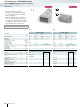
Terminal block gray ST 4/ 2P ① 3042735 50
blue ST 4/ 2P BU ① 3043789 50
Ground terminal green-yellow ST 4/ 2P-PE ② 3042748 50
Accessories
1
)
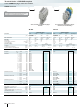
Cover, width 2.2 mm gray D-ST 4 3030420 50
242
PHOENIX CONTACT
Terminal blocks - CLIPLINE complete
4 mm COMBI UT plug-in connection solutions
Notes:
1
) For additional accessories and technical data, see page 240.
2
) For derating curve, visit phoenixcontact.net/products
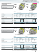
32 A, feed-through terminal block
②
①
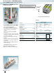
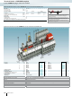
– For the PIN/PIN versions of the COMBI
series, connectors can be used on both
sides of the terminal blocks
– This makes the COMBI system even
more flexible as the terminal blocks are
used as the connection element for
modules
– Connection with standard COMBI
connectors
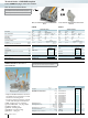
– The extensive range of accessories, such
as latching, strain relief, coding, and shield
connection can be used
– Ground terminals with the same shape
and pitch
– Contact is made free from mechanical and
electrical errors by simply snapping onto
the DIN rail
– All the requirements of IEC60947-7-2
standard are met
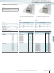
CLIPPROJECTPlanning enables the
quick and convenient planning and
configuration of fault-free terminal strips.
COMBI plug-in PIN/PIN double-level
and ground terminals