
User Manual
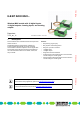


Table Of Contents
- 1 Description
- 2 Table of contents
- 3 Ordering data
- 4 Technical data
- Dimensions
- General data
- Power supply for module electronics
- Wireless interface
- Digital inputs
- Digital outputs
- Analog inputs
- Analog outputs
- Test voltage
- Ambient conditions
- Certification
- Emitted interference in acc. with EN 61000-6-4
- Conformance
- Limitation of simultaneity, derating
- Tolerance of analog inputs and outputs
- 5 Safety regulations and installation notes
- 6 Local diagnostic and status indicators
- 7 Connect supply, actuators, and sensors
- 8 Basic circuit diagram
- 9 Connection example
- 10 Assignment of terminal points to the remote station
- 11 Antennas

ILB BT ADIO MUX...
Preliminary Preliminary Preliminary Preliminary
7173_en_11 PHOENIX CONTACT 2 / 18
2Table of contents
1 Description .............................................................................................................................. 1
2 Table of contents..................................................................................................................... 2
3 Ordering data .......................................................................................................................... 3
4 Technical data ......................................................................................................................... 5
5 Safety regulations and installation notes.................................................................................. 9
5.1 Intended use ...................................................................................................................... 9
5.2 Installation notes ................................................................................................................. 9
5.3 FCC approval ................................................................................................................... 10
5.4 Approval for Japan............................................................................................................. 10
6 Local diagnostic and status indicators................................................................................... 11
7 Connect supply, actuators, and sensors................................................................................ 11
7.1 Terminal point assignment ................................................................................................... 12
8 Basic circuit diagram ............................................................................................................. 13
9 Connection example.............................................................................................................. 13
10 Assignment of terminal points to the remote station .............................................................. 14
11 Antennas ............................................................................................................................... 15
11.1 Omnidirectional antennas .................................................................................................... 15
11.2 Range............................................................................................................................. 18
11.3 Typical combinations of antennas and adapter cables ................................................................ 18