
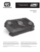
Owner Manual MONOBLOCK AMPLIFIER RSd300.1 RSd600.1
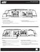

Phoenix Gold International, Inc. • 9300 North Decatur St. Portland, OR 97203 • 503.286.9300 • www.phoenixgold.com
RSd AMPLIFIERS
MONOBLOCK OWNER’S MANUAL
ADJUSTMENTS
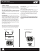
CROSSOVER FREQUENCY SELECTION
Fully variable crossover from 25 to 250Hz. Adjust this setting according to your
speakers specification or to your particular preference.
Figure 6: Crossover and Frequency Selection
INPUT SENSITIVITY ADJUSTMENT
The Input Sensitivity Control is located on the Input Panel. The objective of
the input sensitivity adjustment is to match the output of the source unit with
the input of the amplifier (it is not a volume control). The output voltage of
individual source units can vary. For example, some source units have an
output of 200 mV others have 4 Volts or more. Adjusting this control requires
some experimenting. Basically you want all the gain at the beginning of the
system, NOT at the end (amplifier). Turn your source unit volume UP and keep
your amplifier gains at the minimum possible settings. This will give you the
best sound and signal-to-noise ratio.
Figure 7: Input Sensitivity Control
NOTE: Turning the input gain up does not indicate more power, but increases
the possibility of noise. The input gain control is not a volume control. The
function of the gain is to match the voltage that the amplifier is looking for, to
the voltage that the source unit is supplying
1. Turn the Input Sensitivity Control all the way down (counter clockwise).
2. Set the volume control of the source unit to approximately 3/4 of its
maximum output.
3. Turn the balance control of the source unit to its center position.
4. Set the tone (bass/treble) controls to flat (zero).
5. Play a song (original recording) with wide dynamic range
6. To locate the optimum input sensitivity setting, turn the Input Sensitivity
Control clockwise until audio distortion starts to develop. Turn the sensitivity
control counter clockwise slightly until you no longer hear distortion.
7. If you constantly switch between sources (CD/tape and radio), you will need
further adjustment since radio output level differs from that of CD or tape. In
this case, you need to locate a balanced sensitivity setting which is best for
both the output level of radio and that of CD or tape.
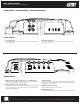
CONNECTING AMPLIFIER POWER WIRE TO THE BATTERY (B+)
Power cables are as important as battery capacity. Use no less than an 8AWG
(8 gauge) power cable, while 4 gauge would be optimum for most applications.
YOU CAN NEVER HAVE TOO BIG OF A POWER/GROUND WIRE! Run the
power cable through the interior of the vehicle (Avoid moving parts: seat rails,
steering column, etc…) connecting one end to the amplifiers (+) terminal and
connecting the other end to a proper sized fuse link within 18 inches of the
positive post on the battery. If possible do not run the power cable together
with the audio cables as it could possibly cause radiated noise in your audio
system. It is recommended to run audio cables on one side of your car and
power cables on the other.
Note: The proper size primary fuse/circuit breaker (located within 18 inches of
the battery) may vary depending on your system design but should not exceed
50% of the main batteries’ amp hour rating. Using a larger value circuit breaker
or fuse value means that you have NO protection. DO NOT over fuse! Fuses on
the amplifier and at the battery DO NOT protect the amplifier, they protect the
car.
CONNECTING AMPLIFIER GROUND WIRE (B-)
It is recommended to run a ground wire directly to the battery as you
would do with the positive cable, to avoid any voltage losses and possible
ground related noises. You can use the vehicle chassis, and if you chose to
do this find a solid ground point (Frame, Strut Tower, Reinforced area near seat/
seatbelt) and remove the paint to reveal bare metal. Attach the ground wire to
the chosen ground source and connect the other end of the ground wire to the
GND terminal of the amplifier.
Note: The ground wire should be the same gauge cable as the power cable
running from the positive post of the battery to the amplifier.
TERMINALS AND CONNECTORS
Proper size terminals and/or connectors are required to ensure a safe and
secure electrical connection and conduction.
CONNECT THE AMPLIFIER REMOTE LEAD (R)
Connect the remote “R” terminal of the amplifier to the remote output lead of
the source unit so that the amplifier will turn on and off with the source unit. If
the source unit does not provide a remote output, connect to the source units’
switched 12+ volt source.
RECONNECT THE BATTERY GROUND TO THE VEHICLE CHASSIS
Double check all the previous installation steps, in particular, the wiring and
component connection. If everything is in order, complete the installation by
reconnecting the battery ground to the vehicle chassis.
Figure 5: Crossover Frequency Selection
Figure 6: Input Sensitivity Control
Both the high-pass and the low-
pass section offer a fully variable
crossover from 40 to 400Hz. Adjust
this setting according to your
speaker component specifications or
to your particular preference.
The Input Sensitivity Control is located on the Input Panel.
The objective of the input sensitivity adjustment is to
match the output of the source unit with the input of the
amplifier (it is not a volume control). The output voltage of
individual source units can vary.
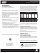
Recommended Cable Size
Total RMS
Power
Distance
4 ft. 8 ft. 12 ft. 16 ft. 20 ft.
100W 8 ga. 8 ga. 8 ga. 8 ga. 4 ga.
200W 8 ga. 8 ga. 8 ga. 4 ga. 4 ga.
400W 8 ga. 8 ga. 4 ga. 4 ga. 4 ga.
600W 8 ga. 4 ga. 4 ga. 4 ga. 4 ga.
800W 4 ga. 4 ga. 4 ga. 2 ga. 2 ga.
1000W 4 ga. 4 ga. 2 ga. 2 ga. 2 ga.
1400W 4 ga. 2 ga. 2 ga. 2 ga. 2 ga.