ZX475Ti Web Manual September 7, 1999
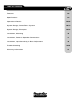
TABLE OF CONTENTS Features 02 Specifications 03 Operational Details 04-05 System Design, PowerFlow tm System 06-07 System Design, Examples 08-15 Installation, Mounting 16 Installation, Power & Speaker Connections 17 Installation, Input Sensitivity & Bass Adjustment 18 19-20 Trouble-Shooting 21 Warranty Information ZXTi amp manual pg.
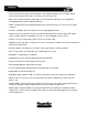
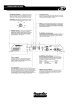
FEATURES • TCCHtm Thermal Convection Cooled Heatsink. This proprietary design uses a variable speed fan to ensure that the ZXTi keeps its cool when the music gets hot! • High-current Triple Darlington output stage. This tried and true topology is the standard for outstanding dynamic peak output performance • TAIMtm Timed Acoustically Integrated Muting. Ensures dead silent turn on & off.
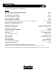
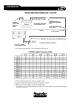
SPECIFICATIONS Continuous Output Power at 1% THD (Wrms): ZX475Ti Into 4 ohms Stereo @ 12.5 Vdc (IASCA/USAC) Into 4 ohms Stereo @ 14.4 Vdc Into 2 ohms Stereo @ 14.4 Vdc Into 4 ohms Bridged @ 14.
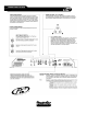
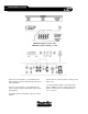
OPERATIONAL DETAILS 220 160 300 450 110 40 800 ZXTi amp manual pg.
OPERATIONAL DETAILS ZXTi amp manual pg.
SYSTEM DESIGN ZXTi amp manual pg.
SYSTEM DESIGN ZXTi amp manual pg.
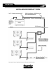
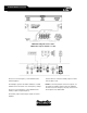
SYSTEM DESIGN examples Minimum bridged load is 2 ohms. Minimum load per channel is 1 ohm. The front crossover frequency control determines the XS62's highpass frequency independently of the XS124 and rear speakers. The rear crossover frequency control determines the XS124's lowpass frequency and auxiliary output's highpass frequency. Use the LPL44 to control the XS124's volume from the driver's seat. * For single preamp headunits, set the input select switch to FRONT.
SYSTEM DESIGN examples Minimum bridged load is 2 ohms. Minimum load per channel is 1 ohm. The front crossover frequency control determines the XS130's highpass. Use the LPL44 to control the auxiliary output's volume from the driver's seat. The bandpass signal for the XS84’s midbass is created between the front and rear crossover frequency settings. NOTE: If connecting tweeters to the front outputs, set the frequency multiplier switch to X10.
SYSTEM DESIGN examples Minimum bridged load is 2 ohms. Minimum load per channel is 1 ohm. The rear crossover frequency control determines the crossover frequencies of all outputs. The auxiliary output sends highpass signals to another amplifier. Use the LPL44 to control the volume of both front and rear outputs. ZXTi amp manual pg.
SYSTEM DESIGN examples Minimum bridged load is 2 ohms. Minimum load per channel is 1 ohm. The front crossover frequency control determines the XS62's highpass frequency independently of the XS69’s and auxiliary outputs. The rear crossover frequency control determines the XS69's highpass frequency and auxiliary output's lowpass frequency. Use the LPL44 to control the auxiliary output's volume from the driver's seat. * For single pre-amp headunits, set the input select switch to FRONT.
SYSTEM DESIGN examples * For single pre-amp headunits, set the input select switch to FRONT. This allows signal from the front inputs to reach the rear channels without the use of “Y” connectors. ZXTi amp manual pg.
SYSTEM DESIGN examples The front crossover frequency control determines the XS62's highpass frequency independently of the XS124 and rear speakers. The rear crossover frequency control determines the XS124's lowpass frequency. Use the LPL44 to control the XS124's volume from the driver's seat. * For single preamp headunits, set the internal select switch to FRONT. This allows signals from the front inputs to reach the rear crossover without the use of “Y” connectors.
SYSTEM DESIGN examples The front crossover frequency control determines the XS62's highpass frequency. The auxiliary outputs send bandpass signals to another amplifier. The rear crossover frequency control determines the XS124's lowpass frequency. Use the LPL44 to control the XS124's volume from the driver's seat. The bandpass signal for the XS84 midbasses is created between the front and rear crossover frequency settings. ZXTi amp manual pg.
SYSTEM DESIGN examples The auxiliary outputs send lowpass signals out to the Bass Cube and then back into the front inputs. The front crossover frequency control determines the XS62's highpass frequency and the XS124's lowpass frequency. NOTE: Locating the Bass Cube in this position of the signal flow allows only the low pass signal for the XS124 to be boosted. The XS62’s high pass signal will be unaffected by the Bass Cube’s boost. Use the LPL44 to control the XS124's volume from the driver's seat.
INSTALLATION ZXTi amp manual pg.
INSTALLATION ZXTi amp manual pg.
INSTALLATION ZXTi amp manual pg.
TROUBLE-SHOOTING SYMPTOM POSSIBLE CAUSE SOLUTION No output and Power-on LEDs are off No battery, ground, or remote connection Verify that the B+, B-, and remote turn-on terminals are properly connected and that the headunit is turned on. Use a DC voltmeter to check for 12 volts between the ground terminal and the B+ terminal. Also, check between the ground terminal and the remote turn-on terminal. Blown or melted power fuse Use an ohmmeter to verify that the fuse has continuity between its ends.
TROUBLE-SHOOTING SYMPTOM POSSIBLE CAUSE Amplifier cuts off when driven to high output levels. Overload circuit activated (red LED on). Excessive output current is the only thing that can cause the Overload LED to light. There are only a few possible causes: SOLUTION A damaged speaker cable touching the vehicle chassis, speaker cables or speaker tinsel leads touching each other, or damaged speaker voice coil.
LIMITED WARRANTY Phoenix Gold International, Inc. (or "Phoenix Gold") warrants its products against defects in materials and workmanship for a limited period of time. For a period of one (1) year from date of original purchase, we will repair or replace the electronic product, at our option, without charge for parts and labor.