Instruction Manual GP EP version version PIPER J3 CUB GP/EP Size .120/20cc Scale 1:4 ¾ ARF SPECIFICATION - Wingspan: 2300mm (90.5in) - Length: 1541mm (60.6 in) - Flying weight: 6000-6500 g - Wing area: 78.6 dm2 - Wing loading: 76.3g/dm2 - Wing type: Naca airfoils - Spinner size: scale type (not included) - Radio: 8 channel minimum (not included) - Servo: 7 standard servo: 2 aileron; 2 flap; 1 elevator; 1 rudder; 1 throttle (not included) - Recommended receiver battery: 6.
Instruction Manual PIPER J3 CUB TABLE OF CONTENTS .......................21 Introduction ....................................................1 Installing the horizontal stab strut Warranty ........................................................2 Installing the engine mount Disclaimer ......................................................2 Installing the fuel tank Safety precaution ............................................2 Installing the throttle pushrod servo Important building notes ......
PIPER J3 CUB Instruction Manual WARRANTY IMPORTANT BUILDING NOTES Phoenix Model guarantees the component parts in this kit to be free from defects in both material and workmanship at the date of purchase by the purchaser. Please trial fit all the parts. Make sure you have the correct parts and that they fit and are aligned properly before gluing! This will assure proper assembly. This kit is hand made from natural materials, every plane is unique and minor adjustments may have to be made.
PIPER J3 CUB Instruction Manual FLIGHT WARNINGS ADHESIVES AND REQUIRED TOOLS When ready to fly, first extend the transmitter aerial. Switch on the transmitter. Switch on the receiver. Check that the wings are correctly fitted to the fuselage. Operate the control sticks on the transmitter and check that the control surfaces move freely and in the CORRECT directions. Check that the transmitter batteries have adequate power. ALWAYS take off into the wind.
PIPER J3 CUB Instruction Manual • Officially designated AMA Air Show Teams (AST) are authorized to use devices and practices as defined within the Team AMA Program Document. (AMA Document #718.) (j) Not operate a turbine-powered aircraft, unless in compliance with the AMA turbine regulations. (AMA Document #510-A.) 3.
PIPER J3 CUB Instruction Manual PREPARATIONS INSTALLING THE AILERONS AND Flaps Use a covering iron with a covering sock on high heat to tighten the covering if necessary. Apply pressure over sheeted areas to thoroughly bond the covering to the wood. 1. Test fit the ailerons to the wing with the hinges. If the hinges don’t remain centered, stick a pin through the middle of the hinge to hold it in position. TEMPORARY PIN TO KEEP HINGE CENTERED 2.
PIPER J3 CUB Instruction Manual 4. Using the thread as a guide and using masking tape, tape the servo lead to the end of the thread: carefully pull the thread out. When you have pulled the servo lead out, remove the masking tape and the servo lead from the thread. INSTALLING THE AILERONs AND FLAPs SERVOS 1. Install the rubber grommets and brass eyelets onto the aileron servo. 5.
PIPER J3 CUB Instruction Manual 2x10mm 2 x 10mm TP Screw 16 < Right Wing > Aileron Servo < Left Wing > Flap Servo Flap Servo Aileron Servo Pull out servo cord with string. Tie the string. Must be purchased separately! Assemble left and right sides the same way Warning! Set all scerws securely. If they come off during flight you will lose control of your aircraft! INSTALLING THE AILERONs AND FLAPs LINKAGES 6.
PIPER J3 CUB Instruction Manual 3 x 25mm Cap Screw 4 2 x 10mm Screw 4 4 2mm Nut 4 4 1.7 x 180mm Push rod 4 Aileron 4 Flap Snap keeper 4 Cut off shaded portion Assemble left and right sides the same way < Bottom view > Neutral 6mm 2x10mm Aileron Rod Aileron Flap Rod Flap Mark the spot to attach. Bend 90 Apply threadlocker (screw cement). Cut off excess.
PIPER J3 CUB Instruction Manual SECURE The Wing To The Fuselage Attach the wings to the fuselage and secure the wing panels. Cut off shaded portion Assemble left and right sides the same way INSTALLING THE MAIN LANDING GEAR 2 x 10mm TP Screw 6 4 x 20mm Cap Screw 4 4mm Washer 4 4mm Spring Washer 4x20mm 4 4x20mm 4mm 5.3mm Collar 4 2 115mm 2x10mm Apply instant glue (CA glue, super glue). Apply threadlocker (screw cement).
PIPER J3 CUB Instruction Manual INSTALLING THE WING STRUT Aluminum ball 4 4 4x15mm 4 4mm 4 4 x 15mm Cap Screw 4 4mm Spring Washer 3 x 10mm Button Screw 4 3 x 12mm TP Screw 4 2 m m 623 59mm m m 623 169mm 3x12mm 3x10mm Plate of plywood Cut off shaded portion 10
PIPER J3 CUB Instruction Manual HORIZONTAL STABILIZER INSTALLATION 6. 1. Using a modeling knife, cut away the covering from the fuselage for the stabilizer and remove it. 2. Draw a center line onto the horizontal stabilizer. 3. Check the fit of the horizontal stabilizer in its slot. Make sure the horizontal stabilizer is square and centered to the fuselage by taking measurements, but don't glue anything yet. 7.
PIPER J3 CUB Instruction Manual Apply instant glue (CA glue, super glue). Secure nylon hinges with instant glue, being careful vertical fin and rudder. Apply epoxy glue Align the center line of vertical fin with rudder. VERTICAL STABILIZER INSTALLATION Installing the rudder using C.A glue as installing the aileron.
PIPER J3 CUB Instruction Manual 90 Degree Apply instant glue (CA glue, super glue). Secure nylon hinges with instant glue, being careful vertical fin and rudder. Align the center line of vertical fin with rudder.
PIPER J3 CUB Instruction Manual 8. Plug the rudder servo into the receiver and center the servo. Install the servo arm onto the servo. INSTALLING THE RUDDER PUSHROD 1. Locate the pushrod exit slot on the right side of the fuselage. 2. 9. Center the rudder and hold it in place using a piece of masking tape. Carefully cut away the covering material from the slot. 10. With the rudder and rudder servo centered, carefully place a mark on the rudder pushrod wire where it crosses the hole in the servo arm.
PIPER J3 CUB Instruction Manual 3x20mm 2x10mm Set all screws securely.
PIPER J3 CUB Instruction Manual Rudder rod Rudder rod Pay close attention here Cut off excess. 7. Locate one nylon servo arm, and using wire cutters, remove all but one of the arms. Using a 2mm drill bit, enlarge the third hole out from the center to accommodate the elevator pushrod wire. INSTALLING THE ELEVATOR PUSHROD 1. Locate the pushrod exit slot on the right side and left side of the fuselage. It is located slightly ahead and below the horizontal stabilizer. 8.
PIPER J3 CUB Instruction Manual 3x20mm 3x20mm 2mm Elevator rod 2x10mm 2x10mm 2mm Assemble left and right sides the same way Apply threadlocker (screw cement).
PIPER J3 CUB Instruction Manual approx. 13mm Elevator Rod Elevator Domino Elevator Servo Rudder Servo Cut off excess.
PIPER J3 CUB Instruction Manual INSTALLING THE Tail wheel 3 x 12mm TP Screw 2 4 x 15mm Cap Screw 3x12mm 2 4mm Spring Washer 2 Spring 2 1 1 4x15mm 4mm 4mm 19 Cut off shaded portion
PIPER J3 CUB Instruction Manual Spring 20
PIPER J3 CUB Instruction Manual INSTALLING THE HORIZONTAL STAB STRUT 3 x 15mm TP Screw 2 4 x 15mm Cap Screw 4x15mm 2 240mm 2 3x15mm 21 Assemble left and right sides the same way
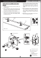
PIPER J3 CUB Instruction Manual INSTALLING THE ENGINE MOUNT 4 x 30mm Screw May be you also need to trim some wood from the tri-angle wood for the installation is easy. 4mm Washer 4mm Spring Washer Engine Mount Engine Mount 4x30mm 4mm 4mm 4x30mm Apply threadlocker (screw cement).
PIPER J3 CUB Instruction Manual INSTALLING THE Fuel Tank 6. When satisfied with the alignment of the stopper assembly tighten the 3mm x 20mm machine screw until the rubber stopper expands and seals the tank opening. Do not over tighten the assembly as this could cause the tank to split. 1. The stopper has been pre-assembled at the factory. 2.
PIPER J3 CUB Instruction Manual Plate of Wood Apply instant glue (CA glue, super glue). INSTALLING THE THROTTLE PUSHROD SERVO 1. Place the engine into the engine mount and align it properly with the front of the cowling. ! If your engine is equipped with a remote needle valve, we suggest installing it into the engine at this time. 2. Slide the pushrod housing through the hole in the firewall, through the hole in the forward bulkhead, and into the servo compartment. PP Pipe 3.
PIPER J3 CUB Instruction Manual INSTALLING THE ENGINE 1.2x500mm Throttle rod 4 x 30mm Screw 1 Locate the long piece of wire used for the throttle pushrod. One end of the wire has been pre-bend in to a "Z" bend at the factory. This "Z" bend should be inserted into the throttle arm of the engine when the engine is fitted onto the engine mount. Fit the engine to the engine mount using the screws provided.
PIPER J3 CUB Instruction Manual Engine Mount DLE 20 4mm 4mm 4x30mm 4x30mm mm 145 DLE 20 Must be purchased separately! 26
PIPER J3 CUB Instruction Manual INSTALLING THE THROTTLE Connector 1. Install one adjustable metal connector through the third hole out from the center of one servo arm, enlarge the hole in the servo arm using a 2mm drill bit to accommodate the servo connector. Remove the excess material from the arm. ! 1 After installing the adjustable metal connector apply a small drop of thin C/A to the bottom nut. This will prevent the connector from loosening during flight. 2.
PIPER J3 CUB Instruction Manual MOUNTING THE COWL 4. While holding the cowl firmly in position, drill four 1,6mm pilot holes through both the cowl and the side edges of the firewall. 1. Remove the muffler and needle valve assembly from the engine. Slide the fiberglass cowl over the engine. 5. Using a 3mm drill bit, enlarge the four holes in the cowling. 2. Measure and mark the locations to be cut out for engine head clearance, needle valve, muffler.
PIPER J3 CUB Instruction Manual Cut off shaded portion Must be purchased separately! INSTALLING THE SPINNER Install the spinner back-plate, propeller and spinner cone. ! The propeller should not touch any part of the spinner cone. If it dose, use a sharp modeling knife and carefully trim away the spinner cone where the propeller comes in contact with it.
PIPER J3 CUB Instruction Manual INSTALLING THE RECEIVER AND BATTERY Receiver Tape 1. Plug the servo leads and the switch lead into the receiver. You may want to plug an aileron extension into the receiver to make plugging in the aileron servo lead easier when you are installing the wing. Plug the battery pack lead into the switch. Foam Pad Tape Foam Pad Battery 2. Wrap the receiver and battery pack in the protective foam to protect them from vibration.
PIPER J3 CUB Instruction Manual Door 31
PIPER J3 CUB Instruction Manual Open and close INSTALLING THE ELECTRIC MOTOR ( EP VERSION ) 4 x 70mm Cap Screw 4 4 x 35mm Cap Screw 4 4mm Washer 8 4mm Spring Washer 8 4 5mm Washer 4mm 12 4x35mm 5mm 10x15mm Aluminum 10x15mm White glue Apply threadlocker (screw cement).
PIPER J3 CUB Instruction Manual 5mm 4mm 4mm 4x70mm 4mm 10x50mm 4mm 4x70mm Must be purchased separately! 33
PIPER J3 CUB Instruction Manual Battery When rotating clock wise, change the connection of 2 wires.
PIPER J3 CUB Instruction Manual BALANCING 3. If the nose of the plane falls, the plane is nose heavy. To correct this first move the battery pack further back in the fuselage. If this is not possible or does not correct it, stick small amounts of lead weight on the fuselage under the horizontal stabilizer. If the tail of the plane falls, the plane is tail heavy. To correct this, move the battery and receiver forward or if this is not possible, stick weight into the firewall.
PIPER J3 CUB Instruction Manual 13mm 13mm Aileron Control 13mm 13mm Elevator Control 40mm 40mm Rudder Control 15mm Flap Control 36
PIPER J3 CUB Instruction Manual FLIGHT PREPARATION PRE FLIGHT CHECK 1. Completely charge your transmitter and receiver batteries before your first day of flying. 2. Check every bolt and every glue joint in your plane to ensure that everything is tight and well bonded. 3. Double check the balance of the airplane 4. Check the control surface 5. Check the receiver antenna . It should be fully extended and not coiled up inside the fuselage. 6. Properly balance the propeller.
PIPER J3 CUB Instruction Manual Main Gear Dimensional Detail 143cm 112cm 53cm TAIL Gear Dimensional Detail 130.0 25.0 49.2 3.0 16.0 9.0 19.0 12.0 49.1 25.
PIPER J3 CUB Instruction Manual DECORATION < Bottom view > < Top view > < Side view > < Side view > 39
EXPLODED VIEW # 26 3x15mm(TP) 2mm 2mm 2x10mm 4x4mm 3x15mm(TP) #6 5mm 10x15mm 4x35mm 4mm 4mm 4mm 10x50mm 4mm 4mm 4mm 4mm 4x30mm 5mm 4mm 4x70mm 4x30mm 4mm 4mm 4mm 4x30mm 3x12mm 4mm 4x20mm 4mm 2x10mm(TP) 4x15mm 40
EXPLODED VIEW 2mm 2x10mm 3x20mm 2mm 2x10mm 3x20mm 3x15mm 4x15mm 3x25mm 2mm 2x10mm 3x25mm 2mm 2x10mm 2x10mm(TP) 2x10mm(TP) 2mm 2x10mm 3x20mm 3x4mm 4mm 4x15mm 2mm 2x10mm 3x25mm 2mm 2x10mm 3x25mm 2x10mm(TP) 2x10mm(TP) 41
I/C FLIGHT WARNINGS Always operate in open areas, away from factories, hospitals, schools, buildings and houses etc. NEVER fly your aircraft close to people or built up areas. THE PROPELLER IS DANGEROUS Keep fingers, clothing (ties, shirt sleeves, scarves) or any other loose objects that could be caught or drawn in, away from the propeller. Take care at ALL times. Keep all onlookers (especially small children and animals) well back from the area of operation.
I/C FLIGHT GUIDELINES When ready to fly, first extend the transmitter aerial. Switch on the transmitter. Operate the control sticks on the transmitter and check that the control surfaces move freely and in the CORRECT directions. ALWAYS land the model INTO the wind, this ensures that the model lands at the slowest possible speed. Check that the transmitter batteries have adequate power. Switch off the receiver. Switch on the receiver. Check that the wings are correctly fitted to the fuselage.