Hl [FR Sgn seat fr Gravity CG: 90-100 mm in} Back from the SPECIFICATION leading edge of the wing, at the fuselage Wingspan: 1490: span: 1490mm (58.
INSTRUCTION MANUAL pL Re dee TE] Flight Wakings. 3 Covering tools. rrr 3 Adhesives and required tools 3 Academy of model aeronautics national model aircraft safety 3 Important notes 5 nd 6 Installing the ailerons. Installing the aileron servos Installing the control ohms. Installing the aileron linkages . Installing the main landing gear . Wing assembly .
INSTRUCTION MANUAL LLL Phoenix Model guarantees the component parts in this kit to be free from defects in both material and workmanship at the date of purchase by the purchaser. This warranty does not cover cosmetic damage or damage due to acts of God, accident, misuse, abuse, negligence, commercial use, or modification of or to any part of the Product. This warranty does not cover damage due to improper installation, operation, maintenance, or attempted repair by anyone other than Phoenix Model.
INSTRUCTION MANUAL Le Lye] * When ready to fly, first extend the transmitter aerial. © Switch on the transmitter. © Switch on the receiver. * Check that the wings are correctly fitted to the fuselage. + Operate the control sticks on the transmitter and check that the control surfaces move freely and in the CORRECT directions. * Check that the transmitter batteries have adequate power. * ALWAYS take off into the wind.
INSTRUCTION MANUAL » Officially designated AMA Air Show Teams (AST) are authorized to use devices and practices as defined within the Team AMA Program Document. (AMA Document #718.) (i) Not operate a turbine-powered aircraft, unless in compliance with the AMA turbine regulations. (AMA Document #510-A) 3.
INSTRUCTION MANUAL PREPARATIONS Use a covering iron with a covering sock on high heat to tighten the covering if necessary. Apply pressure over sheered areas to thoroughly bond the covering to the wood. INSTALLING THE AILERONS 1. Test fit the ailerons to the wing with the hinges. If the hinges don’t remain centered, stick a pin through the middle of the hinge to hold it in position. 2. Apply six drops of thin CA to the top and bottom of each hinge. Do not use CA accelerator.
INSTRUCTION MANUAL A > Make certain the hinges are adequately secured with glue. If they cons loose in flight accidents may result. £3 Secure nylon hinges with instant glue, being careful Apply instant glue (CA slug, super glue). not to glue the wing and aileron together. Align the center line of main wing with aileron. INSTALLING THE AILERON SERVOS 1. Install the rubber grommets and brass eyelets onto the aileron servo. 2.
INSTRUCTION MANUAL 2x 10mm TP Screw = Set all screws securely. If they come off during flight you will lose control of your aircraft! Servo extension cords. (300mm) {8 Pull out servo cord with string. €3 Cut away fim only.
INSTRUCTION MANUAL (3 Pull out servo cord with string. £3 Cutaway film only. here Cut off shaded portion \= J INSTALLING THE CONTROL HORNS 1. One aileron control horn in positioned on each aileron. Using a ruler and a pen, locate and mark the location of the control horn. It should be mounted on the bottom side of the aileron at the leading edge, IN LINE with the aileron push rod. 2. Drill two holes through the aileron using the control hom as a guide and screw the control horn in place. 3.
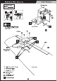
INSTRUCTION MANUAL 2 x20mm TP Screw 1.7x180mm Push rod © Use this hole. 2) Mark the spot to attack (3 Bond 90° Cut off excess. Assemble left and Hg ht bl gl J sides the same way 2 < Bottom view > INSTALLING THE MAIN LANDING GEAR 3 x 8mm Button Screw 30mm Cap Screw (mm Metal wiki link (M2) 5mm Collar 1.7x180mm Push rod Apply threadlike {screw cement}. Apply instant glue 1 (CA glue, super glue}.
INSTRUCTION MANUAL < Wheel well > 3 x 20mm TP Screw ( < Main Gear (L) > < Main Gear (R) > Cut off shaded portion 20) Apply epoxy glue Cut off excess. L4] Assemble left and right "43 sides the same way / WING ASSEMBLY 1) Locate the wing cathedral brace. Using a ruler, locate it's center and place a mark. Draw a vertical *Note* We highly recommend using 30 Minute Epoxy line at the mark just made over faster curing epoxies for several reasons. First, slower curing epoxy is stronger.
INSTRUCTION MANUAL 4) Insert the cathedral brace into one wing half up to the center line. Wipe off any excess epoxy that may have squeezed out of the joint using paper towels. 5) Once the epoxy has cured, trial fit both wing halves together. The center brigs should fit flush together with little or no gaps existing. If gaps do exist, use 220 Grit sandpaper and sand down the high spots on the root ribs and the wing joiner until the proper fit is obtained.
INSTRUCTION MANUAL Ca » Make sure linkages for landing gear are property locked Cut off excess. (3) If linkage rods foul, bend accordingly ta ensure free movement. Retract and the gear is opened. Retract and the gear is closed. INSTALLING SECURE THE WING TO THE FUSELAGE Attach the wings to the fuselage and using the nylon thumbscrews to secure the wing panels. Bx85mm Plastic Screw —] © cut away film only here Cut off shaded portion HORIZONTAL STABILIZER INSTALLATION 1.
INSTRUCTION MANUAL © Secure nylon hinges with Instant glue, being careful tall wing and elevator. 1B] Align the center line of horizontal tail with elevator. {5 Cutaway film only here A » Make certain plane Is aligned accurately per the diagram. A sim-aligned plane can fly mathematical and cause accidents. 20) Apply epoxy glue Cut off shaded portion = Apply instant glue {CA glue, super glue). VERTICAL STABILIZER INSTALLATION 1.
INSTRUCTION MANUAL INSTALLING THE RUDDER PUSH ROD 1. Locate the push rod exit slot on the right side of the fuselage. 2. Carefully cut away the covering material from the slot. 3. Working from inside the fuselage, slide the threaded end of the remaining push rod down the inside of the fuselage until the push rod reaches the exit slot. Carefully reach in with a small screw driver and guide the push rod out of the exit slot. 4. Install the clevis on the rudder push rod.
INSTRUCTION MANUAL Rudder Servo approx. 13mm e 7 Rudder Rod Rudder Must be purchased separately! Cut off shaded portion [& Pay close attention Cut off excess. Sot all screws securely. If they come off during flight you will lose control of your aircraft! INSTALLING THE ELEVATOR PUSH ROD 1. Locate the push rod exit slot on the left side of the fuselage. It is located slightly ahead and below the horizontal stabilizer. 2. Carefully cut away the covering material from the slot. 3.
INSTRUCTION MANUAL approx. 13mm { Fo 90° Emulsify Q Cut off shaded portion £3 Mark the spot to attach {3 Install the hom Ina position so the red Is straight a Pay close attention here KN cut off excess. A. Set all screws securely. If they come off during flight you will lose control of your aircraft! INSTALLING THE NOSE GEAR RETRACT 3 x 20mm TP Crow 1.
INSTRUCTION MANUAL Cut off shaded portion. Must be purchased separately! [a Drill holes with the specified diameter. Cut off excess. H Apply thread ocker Servo steering nose Cable (screw cement).
INSTRUCTION MANUAL INSTALLING THE ENGINE MOUNT May be you also need to trim KH Apply threadlike (screw cement).
INSTALLING THE STOPPER INSTRUCTION MANUAL WARNING Do not overheat, it may break.
INSTRUCTION MANUAL INSTALLING THE FUEL TANK 1. Using a modeling knife, cut one length of silicon fuel line (the length of silicon fuel line is calculated by how the weighted clunk should rest about 5mm away from the rear of the tank and move freely inside the tank). Connect one end of the line to the weighted clunk and the other end to the nylon pick up tube in the stopper. 2. Carefully bend the second nylon tube degrees angle (using a cigarette lighter). This tube will be the vent tube to the muffler. 3.
INSTRUCTION MANUAL » Temporarily install the engine and make a hole for the throttle rod by aligning with the position of the throttle lever. 20) Apply epoxy glue. INSTALLING THE ENGINE Locate the long piece of wire used for the throttle = push rod. One end of the wire has been per-bend [Emm bend at the factory. This "Z" bend = 4 should be inserted into the throttle arm of the 3mm Nut engine when the engine is fitted onto the engine mount. Fit the engine to the engine mount using 8 ee 4 the screws provided.
INSTRUCTION MANUAL INSTALLING THE THROTTLE 1. Install one adjustable metal connector through the third hole out from the center of one servo arm, enlarge the hole in the servo arm using a 2mm drill bit to accommodate the servo connector. Remove the excess material from the arm. AN Avior installing the adjustable metal connector apply a small drop of thin C/A fo the bottom nut. This will prevent the connector from loosening during flight. 2.
INSTRUCTION MANUAL Throttle Serve Screw PP Pipe £3 Adjust the throttle Input (transmitter throttle stick), throttle trim movement and the carburetor opening to the suitable position and screw In the «Throttle Idling > < Throttle Stop > 4x4mm set screw. MOUNTING THE COWL 1. Remove the muffler and needle valve assembly from the engine. Slide the fiberglass cowl over the engine. 2. Measure and mark the locations to be cut out for engine head clearance, needle valve, muffler.
INSTRUCTION 3x 10mm TP Screw Trim the cow! £3 Trim the cowling so it will match your engine INSTALLING THE SPINNER Install the spinner back-plate, propeller and spinner cone. 3x 15mm TP Screw The propeller should not touch any part of the spinner cone. If it dose, use a sharp modeling knife and carefully trim away the spinner cone where the propeller comes in contact with it. Spinner Muffler INSTALLING THE RECEIVER AND BATTERY INSTALLING THE SWITCH 1. Plug the servo leads and the switch lead into the 1.
INSTRUCTION MANUAL Tape Foam Pad Attach securely. A Disconnection during flight will cause loss of control and may result in an accident.
INSTRUCTION MANUAL INSTALLING THE ELECTRIC MOTOR 4x 80mm Cap Screw [mm 4x16mm 4mm Mount Nut 4mm Mount Nut H Apply thread locker Must be purchased (screw cement).
INSTRUCTION MANUAL Electric Speed Controller Must be purchased separately! 3 Follow Instruction manual of Motor and ESC. < Check the motor rotation > Top Hatch When rotating clock wise, change the connection of 2 wires. Motor Lead 1. It is critical that your airplane be balanced correctly. Improper balance will cause your plane to lose control and crash. THE CENTER OF GRAVITY IS LOCATED 90-100mm in) BACK FROM THE LEADING EDGE OF THE WING, AT THE FUSELAGE.
INSTRUCTION MANUAL GC 90-100mm LATERAL BALANCE After you have balanced a plane on the C.G. You should laterally balance it. Doing this will help the airplane track straighter. 5. Turn the airplane upside down. Attach one loop of heavy string to the engine crankshaft and one to the tail wheel wire. With the wings level, carefully lift the airplane by the string. This may require two people to make it easier. 6. If one side of the wing fall, that side is heavier than the opposite.
INSTRUCTION MANUAL 4 CHANNEL RADIO SETUP (STANDARD MODE 2 3, ee ELEVATOR MOVES UP RIGHT AILERON MOVES UP LEFT AILERON MOVES DOWN mm) CARBURETOR WIDE OPEN FLIGHT PREPARATION PRE FLIGHT CHECK 1. Completely charge your transmitter and receiver batteries before your first day of flying. 2. Check every bolt and every glue joint in your plane to ensure that everything is tight and well bonded. 3. Double check the balance of the airplane 4. Check the control surface 5. Check the receiver antenna .