Ii]: CORNING TH. pap BO ko Control throw Ailerons: Low: 12mm up/down, 10% expo; High: 15mm up/down, 10% expo Wingspan: 2410mm (95 in) Control throw Elevators: Low: 12mm up/down, Length: 2177mm (86 in) 12% expo; High: 15mm up/down, 12% expo Flying weight: 11000g-12000g Control throw Rudder: Low: 30mm right/left, Wing area: 96 dm2 15% expo; High: 45mm right/left, 15% expo Wing loading: 115g/dm2 Control throw Flaps: Mid: 15mm down; Wing type: Nazca airfoils Landing: N .
INSTRUCTION MANUAL pr re de SEE] Introduction 1 2 2 Safety precaution . 2 Important building notes. 2 Suggestion 2 Flight wakings. 2 Flight warning; 3 Covering totals. ..3 Adhesives and required tools 3 Academy of mode! aeronautics national model aircraft safety 3 5 Installing the ailerons and 5 Installing the ailerons and flaps servo 7 Installing the aileron and flap linkages.
ION MANUAL LANE Ig Phoenix Model guarantees the component parts in this kit to be free from defects in both material and workmanship at the date of purchase by the purchaser. This warranty does not cover cosmetic damage or damage due to acts of God, accident, misuse, abuse, negligence, commercial use, or modification of or to any part of the Product. This warranty does not cover damage due to improper installation, operation, maintenance, or attempted repair by anyone other than Phoenix Model.
Lx Vela ey © When ready to fly, first extend the transmitter aerial. * Switch on the transmitter. * Switch on the receiver. * Check that the wings are correctly fitted to the fuselage. * Operate the control sticks on the transmitter and check that the control surfaces move freely and in the CORRECT directions. * Check that the transmitter batteries have adequate power. * ALWAYS take off into the wind.
» Officially designated AMA Air Show Teams (AST) are authorized to use devices and practices as defined within the Team AMA Program Document. (AMA Document #718.) Not operate a turbine-powered aircraft, unless in compliance with the AMA turbine regulations. (AMA Document #510-A) 3.
PREPARATIONS Use a covering iron with a covering sock on high heat to tighten the covering if necessary. Apply pressure over sheered areas to thoroughly bond the covering to the wood. 1 Assemble loft and right "43 sides the same way SN INSTALLING THE AILERONS AND FLAPS /N WARNINGS < RIGHT Aileron [© > Please note that C.A glue must be apply to these holes before screw the control hom to the aileron.
RUCTIONS MANUAL 0 Aluminum 68 — o all a f= 3x15mm 0 24 Flap Hom o = Flap Main Wing < Bottom view > Please note that Epoxy glue must be apply to these holes before screw the control hom to the aileron. If not, it comes off during fights, you may lose control of your airplane, resitting in an accident ! \L Flap Ensure smooth, non-binding i movement when assembling KH Apply instant glue (CA glue, super glue).
INSTALLING THE AILERONS AND FLAPS Aileron = Set all screws securely.
3mm Nylon Nut 2 TR 3mm Washer Qe 2 Aluminum ball O3 x 16mm TP Screw (res .
Must be purchased separately! Assemble left and right LA tildes the same way INSTALLING THE PLASTIC COVER ; Lgl Plastic cover P= Set all screws securely. If they come off during flight you wil lose control of your aircraft! rH Apply instant glue (CA glue, super glue).
< Left Wing > i & INSTALLING THE MAIN LANDING GEAR 3 x 10mm Button Screw (om oer 8 6 x 65mm Cap Screw — 6x 4mm ©) 2 6mm Washer OQ) ‘ 4x4mm Set Screw [I eee 2 150 x 100mm Black tape 100 x 100mm Oliver tape < Wheel well > < Main Gear > Cut off shaded parson Apply thread locker {screw cement).
[A] Push pin lke the Illustration £3} Mow to push out the landing gear. Apply threadlike (screw cement nt).
< Main Gear Main Goer (L} > < Main Gear (R) > 2] Apply instant glue {CA slug, super glue).
4x25mm Cap Screw ELECTRIC RETRACT SYSTEM Main Wheel (NT) Power led POWER 7.4v O H Controller Box H Receiver Main Wheel Q = NOSY [ vv lento) Handle \ Assemble left and right = Cut off shaded portion tildes the same way
Decoration for gear door cover.
Remove the |{ covering \ Apply Instant glue 1 (CA glue, super glue).
INSTRUCTION MANUAL INSTALLING THE GUN Assemble left and right LA ides the same way 2 [& Pay close attention
INSTRUCTION MANUAL Adhesive tape Assemble left and right LA sides the same way HORIZONTAL STABILIZER INSTALLATION 1. Using a modeling knife, cut away the covering from the fuselage for the stabilizer and remove it. 2. Remove the covering from the stabilizer. When cutting through the covering to remove it, cut with only enough pressure to only cut through the covering it's self. Cutting into the balsa structure may weaken it. This could lead to possible failure during flight. 3.
INSTRUCTION MANUAL 5. When you are sure that everything is aligned correctly, mix up a generous amount of 30 minute epoxy. Apply a thin layer to the bottom and to the fop of the stabilizer mounting area and to the stabilizer mounting platform sides in the fuselage. Insert the stabilizer in place and re-align. Double check all of your measurements one more time before the epoxy cures. Remove any excess epoxy using a paper towel and rubbing alcohol and hold the stabilizer in place with T-pins or masking tape.
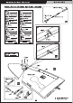
INSTRUCTION MANUAL RUDDER INSTALLATION RY) Apply epoxy glue a > Take off the main wing after put a rudder. INSTALLING THE RUDDER LINKAGES 5. Thread the metal connector to the link ball. The rudder is controlled by two metal cables. Install 6. Center the rudder servo using the radii and the rudder linkages and cables as below. install the servo am. Attach the metal clevis to 1. Use a hobby knife to remove the covering from the the rudder servo arm. openings for the rudder control cables. 7.
INSTRUCTION MANUAL Aluminum ball Ta ay ef 1300mm Cable rod So Lockout OF or 2 3x30mm Connector eee 2 2 Aluminum ball 3x12mm Screw ins Cut off shaded portion 3 Pay close attention here
INSTRUCTION MANUAL INSTALLING THE TAIL WHEEL Aluminum ball 3 x 30mm Connector A airs 2 3mm Nylon Nut 2mm Washer © 4mm Nylon Nut 0 1 E Apply Instant glue (CA glue, super glue).
INSTRUCTION MANUAL Ae Aluminum ball & m rd Cable rad IT = Pls L Rudder en | EY cut off excess.
INSTRUCTION MANUAL INSTALLING THE ELEVATOR PUSH ROD Aluminum ball Se A Aluminum ball Jey ~~ Elevator Rod eg Cut off shaded portion
INSTRUCTION MANUAL INSTALLING THE ELEVATOR SERVO Y — Elevator Servo Must be purchased separately! 25 a Pay close attention here
INSTRUCTION MANUAL SECURE THE WING TO THE FUSELAGE 8mm Plastic Screw HI Remove the covering ~~ Assemble left and right A tildes the same way \.
INSTALLING THE FUEL TANK Fuel Tank 700ce < Front View > Fuel Tank < Top View > 205.0 163.0 69.
INSTRUCTION MANUAL INSTALLING THE ENGINE May be you lase need to trim ‘some wood from the tree-angle wood for the installation is easy.
DLE Electronic Ignition System Dr J) No rod Must be purchased separately EH Apply instant glue (CA glue, super glut. INSTALLING THE THROTTLE 1. Plug the throttle servo into the receiver and turn on the radio system. Check to ensure that the throttle servo output shaft is moving in the correct direction. When the throttle stick is moved forward from idle to full throttle, the throttle barrel should also open and close using this motion. If not, reverse the direction of the servo, using the transmitter.
Throttle red Throttle Servo Apply instant glue (CA glue, super glue). MOUNTING THE COWL 1. Remove the muffler and needle valve assembly from the engine. Slide the fiberglass cowl over the engine. . Measure and mark the locations to be cut out for engine head clearance, needle valve, muffler. Remove the cowl and make these cutouts using a rotary tool with a cutting disc and a rotary sanding drum attachment. . Slide the cowl back into place. Align the front of the cowl with the crankshaft of the engine.
INSTRUCTION MANUAL £3 Trim the cowing so it will match your engine J [[e] Assemble left and right = Cut off shaded portion wm Apply epoxy glue el sides the same way 33
EH Apply instant glue (CA glue, super glue). Assemble left and right 2 sides the same way.
INSTALLING THE SPINNER Install the spinner back-plate, propeller and spinner cone. The propeller should not ouch any part of the spinner cone. If it dose, use a sharp modeling knife and carefully trim away the spinner cone where the propeller comes in contact with it. 3x12mm Button Screw Propeller A = Securely tighten the nut holding the propeller for It not coma off when the motor Is spinning. If coming off, thees Is a high risk of injury! = Always ensure propeller and spinner are balanced.
INSTRUCTION MANUAL Battery for Engine Tape Foam Pad Battery for Receiver > Attach securely. Disconnection EN...
< Check the motor rotation > When rotating clock wise, change the connection of 2 wires.
1. It is critical that your airplane be balanced correctly. Improper balance will cause your plane to lose control and crash. THE CENTER OF GRAVITY IS LOCATED 160mm (6.3 in) BACK FROM THE LEADING EDGE OF THE WING, AT THE FUSELAGE. BALANCE A PLANE UPSIDE DOWN WITH THE FUEL TANK EMPTY. TL Cut off excess. Assemble left and right LA sides the same way = Pay close attention here EH Apply instant glue {CA glue, super glue} 2. If the nose of the plane falls, the plane is nose heavy.
a3 » In order to obtain the CG specified, reposition the receiver and other equipment. » If not obtain the CG specified, add a weight and adjust. A » Do not fly before confirming the correct location of the CG. If the CG is incorrect, you lose control of your airplane which leads to accidents. LATERAL BALANCE After you have balanced a plane on the C.G. You should laterally balance it. Doing this will help the airplane track straighter. 1. Tum the airplane upside down.
22 . 2’ 12mm Ss eT 1 12mm Aileron Control 12mm AI | 12mm Elevator Control ~ — Sez” [30mm EN | 30mm Rudder Control 15mm Flap Control FOR YOUR RADIO INSTALLATION BASIC CONNECTION FOR AIRPLANE AND ADJUSTMENT OF SERVOS Example of connection Witch [30 HM Receiver L] EM Engine ® For more information, refer to radio system instruction manual. @ Follow instruction manual of Engine and Battery.