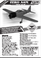
GP/EP Size ARF Control throw Ailerons: Low: 10mm up/down; High: 12mm up/down SPECIFICATION Control throw Elevators: Low: 10mm up/down; Wingspan: 1400mm (55in) High: 12mm up/down Length: 1200mm (47.3 in) Control throw Rudder: Low: 20mm right/left; Flying weight: 2800-2900 g High: 30mm right/left Wing area: 36.8 dm2 Experience level: Intermediate Wing loading: 78g/dm2 Plane type: Scale War bird II Wing type: Nazca airfoils RECOMMENDED MOTOR AND BATTERY SET UP Covering type: Genuine ORACOVER® Motor: RIM FIRE .
INSTR 1ON MANUAL pl Tf lad IE] Introduction 1 Installing the 23 Warranty... 2 Installing the fuel tank 24 ee 2 Installing the throttle push rod servo 25 Safety precaution 2 Installing the engine 26 Important building 2 Installing the end 27 Suggestion... 2 Mounting the cow! 28 Flight 2 Installing the spinner...
INSTRUCTION MANUAL LENS Phoenix Mendel guarantees the component parts in this kit to be free from defects in both material and workmanship at the date of purchase by the purchaser. This warranty does not cover cosmetic damage or damage due to acts of God, accident, misuse, abuse, negligence, commercial use, or edification of or to any part of the Product. This warranty does not cover damage due to improper installation, operation, maintenance, or attempted repair by anyone other than Phoenix Model.
INSTRUCTION MANUAL [xe lL hey * When ready to fly, first extend the transmitter aerial. * Switch on the transmitter. * Switch on the receiver. ® Check that the wings are correctly fitted to the fuselage. » Operate the control sticks on the transmitter and check that the control surfaces move freely and in the CORRECT directions. * Check that the transmitter batteries have adequate power. * ALWAYS take off into the wind.
INSTR 1ON MANUAL « Officially designated AMA Air Show Teams (AST) are authorized to use devices and practices as defined within the Team AMA Program Document. (AMA Document #718.) {i} Not operate a turbine-powered aircraft, unless in compliance with the AMA turbine regulations. (AMA Document #510-A) 3.
INSTRUCTION MANUAL REINFORCE THE FIRE WALL AND PAINTING IMPORTANT NOTES 6 x 200mm Triangular wood CA A Reinforcement of the fire wall using epoxy glue to paste the triangular wood (supped with the kit) to the desired positions In the drawing. A To prevent gasoline from seeping Into the wood, the modeler have to paint the paint on the surface of the wood as shown in the drawing.
INSTRUCTION MANUAL PREPARATIONS Use a covering iron with a covering sock on high heat to tighten the covering if necessary. Apply pressure over sheered areas to thoroughly bond the covering to the wood. INSTALLING THE AILERONS 1. Test fit the ailerons to the wing with the hinges. If the hinges don’t remain centered, stick a pin through the middle of the hinge to hold it in position. 2. Apply six drops of thin CA to the top and bottom of each hinge. Do not use CA accelerator.
INSTRUCTION MANUAL INSTALLING THE AILERON SERVOS 1. Install the rubber grommets and brass eyelets onto the aileron servo. 2. Using a modeling knife, remove the covering from over the per-cut servo am exit hole on the aileron servo tray / hatch. This hole will allow the servo arm to pass through when installing the aileron push rods. 3. Place the servo into the servo tray.
INSTRUCTION MANUAL 210mm 2 x 10mm TP Screw = Set all screws securely. If they come off during flight you will lose control of your aircraft! £3 Cut away film only here. {3 Te the string. {3 Pull out servo cord with string. Must be purchased separately! Assemble left and right A tildes the same way a Cut off shaded portion INSTALLING THE CONTROL HORNS 3. Repeat step install the control hom 1. One aileron control hom in positioned on each on the opposite aileron. aileron.
INSTALLING THE AILERON LINKAGES 8. Insert the 90 degree bend down through the hole in the servo arm. Install one nylon snap keeper over 1. Working with the aileron linkage for now, thread the wire to secure it to the arm. Install the servo one nylon clevis onto one of the 2mm x 180mm arm retaining screw and remove the masking tape threaded wires. from the aileron. 2. Attach the clevis to the outer hole in the control 9. Repeat step install the second aileron hom. linkage.
INSTRUCTION MANUAL INSTALLING THE MAIN LANDING GEAR 3 x 8mm Button Screw 5 x 35mm Cap Screw (mm 3 x 4mm Set Screw mm en 5mm 5mm 5) Apply epoxy glue.
INSTRUCTION MANUAL sides the same way Assemble left and right 7 Apply thread locker {screw comet) He
INSTRUCTION MANUAL Wiki link (M2) silicone 2mm ¥ 3 < Main Gear (L) > < Main Gear (R) > &] Pay close attention here! Lg] Assemble left and right J sides the same way Cut off excess.
< Top view > < Top view > = Ensure that the two wing halves are securely glued together with epoxy. If they come loose in flight accidents may result. Linkage Stopper £3 Temporarily remove. {Tighten the 2 nuts property. {5} supplied with the servo. BF Apply epoxy glue Ta Cutoff shaded portion H Apply thread locker (screw cement). qa Drill holes with the specified diameter. 13 Must be purchased separately! Ensure smooth, non-binding movement when assembling.
a » Marks sure linkages for landing gear are properly locked ree Refract and the gear Is opened. Refract and the gear Is closed. £3 cutoff excess. {3} 1 linkage rods foul, bend accordingly to ensure free movement. SECURE THE WING TO THE FUSELAGE Attach the wings to the fuselage and secure the wing 6mm Plastic Screw panels. — £3 Cut off excess.
HORIZONTAL STABILIZER INSTALLATION 1. Using a modeling knife, cut away the covering from the fuselage for the stabilizer and removes it. 2. Draw a center line onto the horizontal stabilizer. 3. Check the fit of the horizontal stabilizer in its slot. Make sure the horizontal stabilizer is square and centered to the fuselage by taking measurements, but don't glue anything yet. 4.
£3 Secure nylon hinges with instant glue, being careful vertical fin and rudder. {3} Align the center line of vertical fin with rudder. Apply instant glue 1 (CA glue, super glue).
< Bottom view > INSTALLING THE RUDDER PUSH ROD 1. Locate the push rod exit slot on the right side of the fuselage. . Carefully cut away the covering material from the slot. . Working from inside the fuselage, slide the threaded end of the remaining push rod down the inside of the fuselage until the push rod reaches the exit slot. Carefully reach in with a small screw driver and guide the push rod out of the exit slot. . Install the clevis on the rudder push rod.
«< Side view. > < Top view > approx. 13mm & cut away film only. here. {2} Use this hole {3 Install the hom in a position so the rod is straight Cut off excess. Must be purchased separately! Cut off shaded portion A He. LLL Set all screws securely. If they come off during fight you will | * lose control of your aircraft! gm Drill holes with the lm) pacified diameter.
A Set all screws securely. If they come off during flight you will lose control of your aircraft! Supplied with the servo. Neutral I} « Rudder Rod 3 Pay close attention Rudder [) Cut off excess. Must be purchased separately! INSTALLING THE ELEVATOR PUSH ROD 1. 7. Locate the push rod exit slot on the right side and left side of the fuselage. It is located slightly ahead and below the horizontal stabilizer. Carefully cut away the covering material from the slot. .
£3 Cut away film only. here. {Z} Use this hole. @ Install the horn Ina position so the rod is straight. Cut off shaded portion Cut off excess. 7g Assemble left and right be tildes the same way. = Pay close attention Must be purchased separately < Bottom view.
Elevator Serve Set all screws securely. If they come off during flight you will lose control of your aircraft! i foo [3 Pay close attention INSTALLING THE ENGINE MOUNT 2 x 12mm TP Screw Cut off excess.
4 8 3x 15mm TP Screw May be you also need to trim some wood from the tree-angle Drill holes with the specified diameter. Apply instant glue {CA glue, super glue). Note the direction.
INSTRUCTION MANUAL 4 x 25mm Screw 4mm Mount Nut (mmm 4 4mm Washer SJ Engine Mount 4mm Apply thread locker (screw cement).
INSTRUCTION MANUAL . WARNING Do not overheat, it may break. a Cut off shaded portion INSTALLING THE FUEL TANK 1. Using a modeling knife, cut one length of silicon fuel line (the length of silicon fuel line is calculated by how the weighted clunk should rest about 5mm away from the rear of the tank and move freely inside the tank). Connect one end of the line to the weighted clunk and the other end to the nylon pick up tube in the stopper. 2.
INSTRUCTION MANUAL Fuel Tank Clunks #3 Foam ring up = Refer to engine's instruction manual and set up piping. INSTALLING THE THROTTLE PUSH ROD SERVO 1. Place the engine into the engine mount and align it properly with the front of the cowling. A If your engine is equipped with a remote needle valve, we suggest installing it into the engine at this time. 2. Slide the push rod housing through the hole in the firewall, through the hole in the forward bulkhead, and into the servo compartment. 3.
INSTRUCTION MANUAL INSTALLING THE ENGINE 1.2x500mm Throttle rod | | 3x25mm Cap Screw Locate the long piece of wire used for the throttle push rod. One end of the wire has been per-bend bend at the factory. This "2" bend should be inserted into the throttle arm of the — 3mm Nylon Nut engine when the engine is fitted onto the engine . mount. Fit the engine to the engine mount using B Renee 4 the screws provided.
INSTRUCTION MANUAL Throttle Rod Must be purchased separately! INSTALLING THE THROTTLE 1. Install one adjustable metal connector through the third hole out from the center of one servo arm, enlarge the hole in the servo arm using a 2mm drill bit to accommodate the servo connector. Remove the excess material from the arm. After installing the adjustable metal connector apply a small drop of thin C/A fo the bosom nut. This will prevent the connector from loosening during flight. 2.
INSTRUCTION MANUAL Throttle servo | 00 00 £3 Adjust the throttle Input (transmitter throttle stick), throttle trim movement and the carburetor opening to the suitable position and screw in the 4x4mm set screw. X Must be purchased separately! PP Pipe < Throttle Idling > Throttle position of Tx. approx. "E 2 ! Throttle Servo | fo < Throttle Hi > < Throttle Stop > Carburetor MOUNTING THE COWL /\ Enraging the holes through the cowl will prevent 1. Remove the muffler and needle valve assembly from the engine.
© Trim the cowling so it will match your engine Plate of plywood &] Pay close attention here! 2 Cut off shaded portion ow Apply epoxy glue
¥ Apply epoxy glue rH Apply instant glue {CA glue, super glucose. 4 Assembly left and right "45 sides the same way. [ll Drill holes with the specified diameter.
INSTALLING THE SPINNER 3x12mm Install the spinner back-plate, propeller and spinner cone. The propeller should not touch any part of the spinner cone. If it dose, use a sharp modeling knife and carefully trim away the spinner cone where the propeller comes in contact with it. Spinner Spinner Must be purchased separately! 3x12mm TP Screw » Usa the spacer suitable for shaft > Securely tighten the nut holding the propeller for It not coma off wham the motor Is spinning.
Tape Foam Pad Battery Tape Receiver. Foam Pad ON... Attach securely. Disconnection during flight will cause loss of control and may recur In an accident o ie = Switch Must be purchased separately 3x 15mm Cap Screw 4 x 60mm Cap Screw H White glue Apply thread locker (screw cement).
INSTRUCTION MANUAL 1. It is critical that your airplane be balanced 3. correctly. Improper balance will cause your plane to lose control and crash. THE CENTER OF GRAVITY IS LOCATED 90mm { 3.54 in) BACK FROM THE LEADING EDGE OF THE WING, AT THE FUSELAGE. BALANCE A PLANE UPSIDE DOWN WITH THE FUEL TANK EMPTY. 2. Mount the wing to the fuselage. Using a couple of pieces of masking tape, place them on the top side of the wing 90mm { 3.54 in) back from the leading edge, at the fuselage sides.
INSTRUCTION MANUAL Aileron Control Ne Lg? 10mm TR 1 10mm Elevator Control — S ol 20mm CT, 20mm WN to Rudder Control
INSTRUCTION MANUAL 4 CHANNEL RADIO SETUP (STANDARD MODE 2) FLIGHT PREPARATION PRE FLIGHT CHECK 1. Completely charge your transmitter and receiver batteries before your first day of flying. 2. Check every bolt and every glue joint in your plane to ensure that everything is tight and well bonded. 3. Double check the balance of the airplane. Check the control surface. 5. Check the receiver antenna. It should be fully extended and not coiled up inside the fuselage. 6. Properly balance the propeller.