AUTOMATIONWORX User Manual UM EN FL SWITCH LM Order No.
AUTOMATIONWORX User Manual Hardware and Software of Lean Managed Switches 05/2007 Designation: UM EN FL SWITCH LM Revision: 01 Order No.: 2888851 This user manual is valid for: Designation Order No.
FL SWITCH LM Please Observe the Following Notes In order to ensure the safe use of the product described, we recommend that you read this manual carefully. The following notes provide information on how to use this manual.
FL SWITCH LM General Terms and Conditions of Use for Technical Documentation Phoenix Contact GmbH & Co. KG reserves the right to alter, correct, and/or improve the technical documentation and the products described in the technical documentation at its own discretion and without giving prior notice, insofar as this is reasonable for the user. The same applies to any technical changes that serve the purpose of technical progress.
FL SWITCH LM Statement of Legal Authority This manual, including all illustrations contained herein, is copyright protected. Use of this manual by any third party is forbidden. Reproduction, translation, and public disclosure, as well as electronic and photographic archiving or alteration requires the express written consent of Phoenix Contact. Violators are liable for damages. Phoenix Contact reserves all rights in the case of patent award or listing of a registered design.
Table of Contents Table of Contents 1 2 3 Lean Managed Switch ............................................................................................................1-1 1.1 Properties........................................................................................................... 1-1 1.1.1 Front View/Operating Elements/Slots for the LMS .............................1-2 1.1.2 Dimensions of the LMS ...................................................................... 1-3 1.1.
FL SWITCH LM 3.4 4 5 Management via Local V.24 (RS-232) Communication Interface ......................................................... 3-51 3.4.1 General Function ..............................................................................3-51 3.4.2 User Interface Functions ..................................................................3-52 3.4.3 Starting With Faulty Software ........................................................... 3-55 Rapid Spanning Tree ....................................
Lean Managed Switch 1 Lean Managed Switch 1.1 Properties The Lean Managed Switch (LMS) is an Ethernet switch, which is suitable for industrial use.
FL SWITCH LM Features and Fields of Application of the LMS – – – – – Increased network performance by filtering data traffic: - Local data traffic remains local. - The data volume in the network segments is reduced. Easy network expansion and network configuration. Coupling segments with different transmission speeds. Automatic detection of 10 Mbps or 100 Mbps data transmission rate for RJ45 ports.
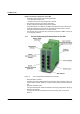
Lean Managed Switch – – Alarm contact/functional earth ground The floating alarm contact and the optional functional earth ground can be connected here via the COMBICON connector. Supply voltage connection The supply voltage can be connected redundantly via the 4-pos. COMBICON connector as an option. 1.1.2 Dimensions of the LMS 112 mm (4.409") 45 mm (1.772") 99 mm (3.898") US1 US2 75500002 Figure 1-3 7278_en_01 8 1 7 2 6 3 5 4 FL LM58TX-E FLSWITCH SWITCH TX Ord.-No.2891466 Ord. No.
FL SWITCH LM 1.1.3 Status and Diagnostic Indicators Des. Color US1 Green US2 LNK Status Green Green ON Supply voltage US1 in the tolerance range OFF Supply voltage US1 less than 18 V DC ON Supply voltage US2 in the tolerance range OFF Supply voltage US2 less than 18 V DC ON Link active OFF Link not active Flashing 100 1.1.
Lean Managed Switch 1.2 Assembly/Removal 1.2.1 Assembly and Removal of the LMS Mount the LMS on a clean DIN rail according to DIN EN 50 022 (e.g., NS 35 ... from Phoenix Contact). To avoid contact resistance only use clean, corrosion-free DIN rails. Before mounting the modules, an end clamp (E/NS 35N, Order No. 0800886) should be mounted on the left-hand side next to the LMS to stop the modules from slipping on the DIN rail.
FL SWITCH LM 1.2.3 1. 2. Removal Remove all connectors. Pull down the positive latches using a suitable tool (e.g., screwdriver). Both positive latches remain snapped out. Then swivel the bottom of the module away from the DIN rail slightly (A). Next, lift the module upwards away from the DIN rail (B). C A B Figure 1-5 1.3 Installing the Lean Managed Switch 1.3.1 Connecting the Supply Voltage 1.3.1.
Lean Managed Switch 1 OUT 24 V DC 2 opt. OUT 24 V DC US1 opt. US1 72780003 Figure 1-6 1.3.2 LMS supply Alarm Contact The switch has a floating alarm contact. Under normal conditions, the contact is closed allowing current to flow. When power is lost, the contact opens, indicating an error. R 1 R 2 6 7 8 4 0 0 1 5 Figure 1-7 Circuit diagram for the alarm contact In the event of non-redundant power supply, the switch indicates a supply voltage failure by opening the alarm contact.
FL SWITCH LM 1.3.3 V.24 (RS-232) Interface for External Management The 6-pos. Mini-DIN female connector provides a serial interface to connect a local management station. Use the "PRG CAB MINI DIN" programming cable (Order No. 2760611). It can be used to connect a VT100 terminal or a PC with corresponding terminal emulation to the management interface (for an appropriate cable, please refer to "Ordering Data" on page 6-2).
Startup and Functions 2 Startup and Functions By default upon delivery the IGMP Snooping function is activated for the „E“ versions. It can be activated in the WBM for the other versions, if necessary. 2.1 Basic Settings The basic Ethernet functions do not have to be configured and are available when the supply voltage is switched on. 2.1.
FL SWITCH LM 2.1.2.1 Valid IP Parameters IP parameters comprise the following three elements: "IP address", "subnet mask", and "default gateway/router". Valid IP addresses are: 000.000.000.001 to 126.255.255.255 128.000.000.000 to 223.255.255.255 Valid multicast addresses are: 224.000.000.001 to 239.255.255.255 Valid subnet masks are: 255.000.000.000 to 255.255.255.252 Default gateway/router: The IP address of the gateway/router must be in the same subnetwork as the address of the switch. 2.1.2.
Startup and Functions IP addresses can be represented in decimal or hexadecimal form. In decimal notation, bytes are separated by dots (dotted decimal notation) to show the logical grouping of the individual bytes. The decimal points do not divide the address into a network and user address. Only the value of the first bits (before the first "zero") specifies the network class and the number of remaining bits in the address. Possible Address Combinations Class A 0.0.0.0 - 127.255.255.
FL SWITCH LM 2.1.2.3 Special IP Addresses for Special Applications Certain IP addresses are reserved for special functions. The following addresses should not be used as standard IP addresses. 127.x.x.x Addresses The Class A network address "127" is reserved for a loopback function on all computers, regardless of the network class. This loopback function may only be used on networked computers for internal test purposes.
Startup and Functions Application If the ANDing of the address bits gives the local network address and the local subnetwork address, the device is located in the local network. If the ANDing gives a different result, the data telegram is sent to the subnetwork router. Example for a Class B subnet mask: Decimal representation: 255.255.192.0 Binary representation: 1111 1111.1111 1111.1100 0000.
FL SWITCH LM 2.1.3 Flowchart After a Restart 2.1.3.
Startup and Functions 2.1.3.2 Assigning IP Parameters Startup Yes IP parameters received from BootP server No Three requests remain unanswered? Yes Yes Is there a valid local IP address? Yes Entry of IP parameters as local configuration No Assignment of IP parameters via V.
FL SWITCH LM 2.2 Frame Switching The managed switch operates in store-and-forward mode. When receiving a data packet, the switch analyzes the source and destination addresses. The switch stores up to 1023 MAC addresses with an aging time of 48 seconds in its address table. 2.2.1 Store-and-Forward All data telegrams that are received by the switch are saved and their validity is checked. Invalid or faulty data packets (> 1522 bytes or CRC errors) and fragments (< 64 bytes) are rejected.
Startup and Functions Flowchart for "Learning Addresses" Using the Example of Unicast Addresses Switch receives a frame at port 1 Search for destination address in the address table. Found? No Yes The assigned port is receive port (port 1) Check which port the address is assigned to.
FL SWITCH LM 2.2.4.1 VLAN/Prioritization Tag The LMS processes incoming data packets with regard to prioritization information contained in the Ethernet packet (VLAN/prioritization tag). The tag enables the specification of a priority level from 0 to 7, which the LMS assigns to one of its two internal queues. By default upon delivery, the packets with priorities from 0 to 3 are treated as low-priority packets whereas packets with priorities from 4 to 7 are highpriority Ethernet packets.
Configuration and Diagnostics 3 Configuration and Diagnostics Lean Managed Switches offer several user interfaces for accessing configuration and diagnostic data. The preferred interfaces are the web interface and SNMP interface. These two interfaces can be used to make all the necessary settings and request all information. Access via V.24 (RS-232) interface only enables access to basic information. However, the V.
FL SWITCH LM Figure 3-1 Messages from the LMS in the Factory Manager Right-click on one of the LMS messages and select the "Add new device..." menu item. Under "Description", select an icon and enter a device name. Specify the desired IP parameters under "TCP/IP" (see also "Assigning IP Parameters" on page 3-1). Figure 3-2 Input mask for IP parameters Make sure that the assignment of IP parameters via BootP is also activated.
Configuration and Diagnostics Once you have clicked on "Add", the device is added to the project and is indicated as unavailable. You must now restart or reset the LMS. Following a restart, the LMS resends the BootP requests and receives the corresponding BootP reply from the Factory Manager. Once the boot process has been completed the LMS is indicated as available. If the LMS is still indicated as "unavailable", check your network card settings.
FL SWITCH LM System Figure 3-4 "System" menu In this menu, you can add additional information in the white fields, which will be saved on the LMS. This information is also available via SNMP and WBM.
Configuration and Diagnostics Information about the device status and redundancy is displayed here. All the messages for this device are displayed under Messages. Trap Targets Figure 3-6 "Trap Targets" menu Trap targets are displayed or set here, and the "send traps" function can be activated or deactivated. Clicking on "Set Default Values" automatically activates the IP address of the computer on which the Factory Manger is installed as the trap target.
FL SWITCH LM Firmware Figure 3-7 "Firmware" menu Here you can view all information about the current device software (firmware). You can also update the software using the Factory Manager. Firmware update When you click on "Update", the following window appears, which contains information about the firmware used. Please make sure that the "TFTP Server" service program is activated in the toolbar. Following a firmware update, a reset is executed automatically to activate the new firmware.
Configuration and Diagnostics Update Figure 3-8 "Update" menu In order to enable a firmware update, the firmware image must be located in the "Download" directory of the Factory Manager. 3.2 3.2.1 Online diagnostics Web-Based Management (WBM) General Function The user-friendly web-based management interface can be used to manage the switch from anywhere in the network using a standard browser. Comprehensive configuration and diagnostic functions are clearly displayed on a graphic user interface.
FL SWITCH LM 3.2.2 Requirements for the Use of WBM As the web server operates using the Hyper Text Transfer Protocol, a standard browser can be used. Access is via the URL "http://IP address of the device". Example: "http://172.16.29.112". For full operation of the web pages, the browser must support JavaScript 1.2 and cascading style sheets Level 1. We recommend the use of Microsoft Internet Explorer 6.0. WBM can only be called using a valid IP address.
Configuration and Diagnostics 3.2.2.2 Password Concept After having entered the valid password, no further entry of the password is necessary for a period of 300 s (default). After this period of time has elapsed or after clicking on "Logout", the password must be re-entered. The period of time can be set using the "flWorkFWCtrlLoginExpire" SNMP object within a range of 30 s to 3600 s (default 300 s). The concept is valid for the first ten users.
FL SWITCH LM 3.2.3.1 Figure 3-9 General Instructions "Information" web page Contains a brief description of WBM and a navigation tree (site map), which is linked to every page of WBM. 3.2.3.2 Figure 3-10 Device Information "Device Information" web page "General" Menu This page contains a range of static information about the device and the manufacturer.
Configuration and Diagnostics "Local Diagnostics" Menu This page describes the meaning of the diagnostic and status indicators. Figure 3-11 "Local Diagnostics" web page "Serial Port" Menu This page lists the transmission parameters for serial communication.
FL SWITCH LM 3.2.3.3 General Configuration "IP Configuration" Menu This page displays the set IP parameters and addressing mechanism. To change the IP parameters via WBM, "Static" assignment must be selected. Figure 3-13 "IP Configuration" web page If you modify the IP address and/or the other IP parameters via WBM, once you click on "Apply" you will no longer have access via the IP address set in the browser.
Configuration and Diagnostics Trap configuration This part of the table is used to view or modify the IP addresses of the two trap receivers. It is also used to activate/deactivate the "send traps" function. "Software Update" Menu This page is used to view or modify the parameters for a software update and to trigger the update. Figure 3-15 3.2.4 "Software Update" web page Executing the Firmware/Software Update Requirements The device must have valid IP parameters so that the firmware can be updated.
FL SWITCH LM • Enter the device password (default: „private“) and click with the mouse on „Apply“. Figure 3-17 Web interface with the update parameters Next this window. Figure 3-18 • Message after a successful update Close the WBM and re-start it. Please make sure that the "TFTP Server" service program is activated in the Factory Manager toolbar. Firmware update can take several minutes. You can monitor the download in the Factory Manager message window (25%, 50%, 75%, 100%).
Configuration and Diagnostics "Change Password" Menu This option can be used to specify the current password and then enter a new, unique password. By default upon delivery, the password is "private" (please note that it is casesensitive). For security reasons, the input fields do not display your password, but instead "*******" is displayed. Figure 3-19 "Change Password" web page The password must be between four and twelve characters long.
FL SWITCH LM "General Configuration/Configuration Management" Menu This table is used to view all parameters that are required to save the active configuration or load a new configuration, and to modify them (by entering a valid password). It can also be used to restart the system with the relevant configuration. Figure 3-21 "Configuration Management" web page Possible States for "Status of current configuration": – – – – The configuration has been modified but not saved.
Configuration and Diagnostics Load the last stored configuration This option can be used to reload the last configuration saved on the device or the PC. All modifications made to the configuration since it was last saved are lost. Figure 3-23 "Load the last stored configuration" web page "General Configuration/Configuration Management/File Transfer" Menu When a configuration is uploaded from the LMS to a PC, the last saved version is transmitted.
FL SWITCH LM Configuration using a configuration file is used when replacing devices. To duplicate devices using a configuration file, observe the following: – Establish a point-to-point connection between an LMS and the management station. – Load the configuration file to the LMS. – Reset the LMS. – Adjust the IP parameters. – Save the configuration ("Save current configuration" function). The duplicated switch can now be operated in the network using the adjusted IP parameters. 3.2.4.
Configuration and Diagnostics Figure 3-25 Port Configuration "Port Configuration Table" web page Individual configuration option for each port. To view detailed data traffic statistics for the selected port, click on "Port Statistics". Even if the port is switched off, the Link LEDs for the port remains active.
FL SWITCH LM "Ports/Port Statistics" Menu (only FL SWITCH LM ...) This menu provides detailed statistical information about the volume of data for each individual port. On this page, additional counter states can be set to zero for all ports..
Configuration and Diagnostics "Ports/Port Mirroring" Menu Activation/deactivation and setting of port mirroring. Port mirroring is used to passively read incoming or outgoing data that is being transmitted via the selected ports. To do this a measuring instrument (PC) is connected to the destination port, which records the data, yet must not itself be activated. Figure 3-28 "Port Mirroring" web page If ports are set with the same value, port mirroring will be disabled. The source port is set to "0".
FL SWITCH LM "Diagnostics/Alarm Contact" Menu Here, you can set whether and for which events the alarm contact can be used. Figure 3-30 "Alarm Contact" web page Click on the "Switch Station / Ports / Port Table" link (on "Alarm Contact" page in WBM) to access the port configuration page. "Utilization" Menü Here, the network capacity of every individual port is displayed as bargraph. The display is automatically updated in accordance with the refresh intervals.
Configuration and Diagnostics 3.2.4.2 Rapid Spanning Tree / Multicast Filtering For information about (Rapid) Spanning Tree, please refer to Section 4 "Rapid Spanning Tree". For information about Multicast Filtering, please refer to Section 5 "Multicast Filtering".
FL SWITCH LM 3.3 3.3.1 Simple Network Management Protocol (SNMP) General Function SNMP is a manufacturer-independent standard for Ethernet management and defines commands for reading and writing error and status message information and formats. SNMP is also a structured model, which comprises agents and their relevant MIB (Management Information Base) and a manager. The manager is a software tool, which is executed on a network management station.
Configuration and Diagnostics Reading SNMP objects is not password-protected. However, a password is required for read access in SNMP, but this is set to "public", which is usual for network devices, and cannot be modified. By default upon delivery, the password for write access is "private" and can be changed by the user. SNMP, the web interface, Telnet, and the serial terminal all use the same password, which can be changed by the user.
FL SWITCH LM 3.3.2 Diagram of SNMP Management Management station SNMP management Trap receiver SNMP traps Management objects organized in MIBs US1 US2 8 1 7 2 6 3 5 4 MIB FL SWITCH LM 8TX Ord.-No.2832632 FL SWITCH 5 TX Ord. No.2832085 Agent Agent US UM US FL IL 24 BK-B Ord.-No.: 2833000 1 US 1 PP 2 FAIL 1 1 2 2 XMT 100 1 2 2 3 4 4 10/100 LINK 100 1 2 1 XMT RCV 3 1 FAIL 1 XMT RCV UM FL IL 24 BK-B Ord.-No.: 2833000 PP 2 FAIL LINK UM FL IL 24 BK-B Ord.
Configuration and Diagnostics 3.3.2.1 Tree Structure of the MIB 1 iso 0 std 3 org 8802 iso8802 6 dod 1 ieee802dot1 1 internet 1 ieee802dot1mibs 2 mgmt 4 private 6 snmpV2 1 mib-2 1 enterprises 3 snmpModules 4346 phoenixContact 1 snmpMIB 2 lldpMIB 1 system 72780016 2 interfaces 3 address translation 4 ip 5 icmp 6 tcp 7 udp 8 egp 10 transmission 11 snmp 17 dot1dBridge 30 ianaifType Figure 3-33 Tree structure of the MIB Not all devices support all object classes.
FL SWITCH LM 3.3.3 RFC1213-MIB - MIB II 3.3.3.1 System Group (1.3.6.1.2.1.1) The system group has mandatory characters for all systems. It contains system-specific objects. If an agent does not have a value for a variable, the response is a string with length 0. (1) system – (1) sysDescr – (2) sysObjectID – (3) sysUpTime – (4) sysContact – (5) sysName – (6) sysLocation – (7) sysServices – (8) sysORLastChange – (9) sysORTable sysDescr OID 1.3.6.1.2.1.1.1.
Configuration and Diagnostics sysContact OID 1.3.6.1.2.1.1.4.0 Syntax Octet string (size: 0 - 255) Access Read and write Description The textual identification of the contact person for these managed nodes and information on how this person can be contacted. sysName OID 1.3.6.1.2.1.1.5.0 Syntax Octet string (size: 0 - 255) Access Read and write Description A name for this node assigned by the administrator. According to the agreement, this is the fully qualifying name in the domain.
FL SWITCH LM 3.3.3.2 Interface Group (1.3.6.1.2.1.2) The interface group contains information about device interfaces.
Configuration and Diagnostics 3.3.4.2 dot1dStp (1.3.6.1.2.1.17.
FL SWITCH LM -- (2) dot1dTpPortMaxInfo -- (3) dot1dTpPortInFrames -- (4) dot1dTpPortOutFrames -- (5) dot1dTpPortInDiscards (5) dot1dTpHCPortTable -- dot1dTpHCPortEntry -- (1) dot1dTpHCPortInFrames -- (2) dot1dTpHCPortOutFrames -- (3) dot1dTpHCPortInDiscards (6) dot1dTpPortOverflowTable -- dot1dTpPortOverflowEntry -- (1) dot1dTpPortInOverflowFrames -- (2) dot1dTpPortOutOverflowFrames -- (3) dot1dTpPortInOverflowDiscards 3.3.4.5 dot1Static (1.3.6.1.2.1.17.
Configuration and Diagnostics 3.3.5 Private MIBs The private MIBs for the LMS from Phoenix Contact can be found under object ID 1.3.6.1.4.1.4346. The LMS MIB contains the following groups: – pxcModules (OID = 1.3.6.1.4.1.4346.1) – pxcGlobal (OID = 1.3.6.1.4.1.4346.2) – pxcFactoryLine (OID = 1.3.6.1.4.1.4346.11) All configuration modifications, which are to take effect after an LMS restart, must be saved permanently using the "flWorkFWCtrlConfSave" object.
FL SWITCH LM Access Read Description Contains the manufacturer's name: Phoenix Contact GmbH & Co. KG. pxcBasicDescr OID 1.3.6.1.4.1.4346.2.1.2 Syntax Display string Access Read Description Contains the manufacturer's name and address: Phoenix Contact GmbH & Co. KG P.O. Box 1341 D-32819 Blomberg. pxcBasicURL OID 1.3.6.1.4.1.4346.2.1.3 Syntax Display string Access Read Description Contains the manufacturer's web address: http://www.phoenixcontact.com. 3.3.5.3 pxcFactoryLine OID = 1.3.6.1.
Configuration and Diagnostics Description Contains a brief description of the product group: Ethernet Installation System. flBasicURL OID 1.3.6.1.4.1.4346.11.1.1.3 Syntax Display string Access Read Description Contains a specific URL for the product group: www.factoryline.de. flBasicCompCapacity OID 1.3.6.1.4.1.4346.11.1.1.4 Syntax Integer32 (1 - 1024) Access Read Description Contains the number of different components that can be managed with this device. flComponents OID 1.3.6.1.4.1.
FL SWITCH LM Syntax Display string Access Read Description Contains a brief description of the component. flComponentsURL OID 1.3.6.1.4.1.4346.11.1.2.1.1.4 Syntax Display string Access Read Description Contains the URL of a website with additional information: www.factoryline.de. flComponentsOrderNumber OID 1.3.6.1.4.1.4346.11.1.2.1.1.5 Syntax Display string Access Read Description Contains the Order No. of the component. flWorkDevice OID 1.3.6.1.4.1.4346.11.11 flWorkBasic OID 1.3.
Configuration and Diagnostics flWorkBasicSerialNumber OID 1.3.6.1.4.1.4346.11.11.1.4 Syntax Octet string (12) Access Read Description Contains the serial number of the device. flWorkBasicHWRevision OID 1.3.6.1.4.1.4346.11.11.1.5 Syntax Octet string (4) Access Read Description Contains the hardware version of the device. flWorkBasicPowerStat OID 1.3.6.1.4.1.4346.11.11.1.
FL SWITCH LM flWorkNetIfParamPhyAddress OID 1.3.6.1.4.1.4346.11.11.4.1.1 Syntax MAC address Access Read Description Contains the MAC address of the switch. flWorkNetIfParamIPAddress OID 1.3.6.1.4.1.4346.11.11.4.1.2 Syntax IP address Access Read/write Description Contains the current IP address of the LMS. Modifications only take effect once the "flWorkNetIfParamSave" object has been executed.
Configuration and Diagnostics flWorkNetIfParamStatus OID 1.3.6.1.4.1.4346.11.11.4.1.5 Syntax Integer32 (1 - 1024) Access Read Description Indicates whether the IP parameters have been modified but not saved: - No change - Address setting modified, but not yet activated 1 2 Address settings must be saved permanently using the "flWorkFWCtrlConfSave" object. flWorkNetIfParamSave OID 1.3.6.1.4.1.4346.11.11.4.1.
FL SWITCH LM flWorkNetPortCapacity OID 1.3.6.1.4.1.4346.11.11.4.2.1 Syntax Integer32 (1 - 1024) Access Read Description Contains the number of available ports depending on the configuration of the LMS. flWorkNetPortTable OID 1.3.6.1.4.1.4346.11.11.4.2.2 flWorkNetPortEntry OID 1.3.6.1.4.1.4346.11.11.4.2.2.1 Description Generates a table with a detailed description of the port configuration. flWorkNetPortIndex OID 1.3.6.1.4.1.4346.11.11.4.2.2.1.
Configuration and Diagnostics Description Contains the duplex mode of the selected port: Automatic 1 Manual 2 flWorkNetPortName OID 1.3.6.1.4.1.4346.11.11.4.2.2.1.6 Syntax Octet string (0 - 16) Access Read/write Description Contains the "name" of the port, e.g., "Robot 1". flWorkNetPortEnable OID 1.3.6.1.4.1.4346.11.11.4.2.2.1.7 Syntax Integer Access Read/write Description Here you can disable the port: Port disabled Port enabled 1 2 flWorkNetPortLinkMonitoring OID 1.3.6.1.4.1.4346.11.
FL SWITCH LM Access Read Description Contains the index of the port according to IEEE 802.3ad. flWorkNetPortType OID 1.3.6.1.4.1.4346.11.11.4.2.2.1.13 Syntax Octet string Access Read Description Specifies the medium of this port. flWorkNetPortModuleName OID 1.3.6.1.4.1.4346.11.11.4.2.2.1.14 Syntax Octet string Access Read Description Specifies the "name" of the module. flWorkNetPortInterfaceName OID 1.3.6.1.4.1.4346.11.11.4.2.2.1.
Configuration and Diagnostics flWorkFWInfoVersion OID 1.3.6.1.4.1.4346.11.11.11.1.1 Syntax Octet string (4) Access Read Description Contains the firmware version as a string. Example for Version "3.97": 0x33, 0x2e, 0x39, 0x37. flWorkFWInfoState OID 1.3.6.1.4.1.4346.11.11.11.1.2 Syntax Octet string (6) Access Read Description Contains the firmware release as a string. Example for "beta": 0x62, 0x65, 0x64, 0x61. flWorkFWInfoDate OID 1.3.6.1.4.1.4346.11.11.11.1.
FL SWITCH LM flWorkFWInfoBootVersion OID 1.3.6.1.4.1.4346.11.11.11.1.6 Syntax Octet string (4) Access Read Description Contains the version of the Boot loader as a string. Example for Version "2.65": 0x32, 0x2e, 0x36, 0x35. flWorkFWInfoBootState OID 1.3.6.1.4.1.4346.11.11.11.1.7 Syntax Octet string (6) Access Read Description Contains the Boot loader release as a string. Example for "beta": 0x62, 0x65, 0x64, 0x61. flWorkFWInfoBootDate OID 1.3.6.1.4.1.4346.11.11.11.1.
Configuration and Diagnostics flWorkFWCtrlReset OID 1.3.6.1.4.1.4346.11.11.11.2.1.1 Syntax Integer Access Read/write Description With write access, a reset can be executed with "2". With read access, the value is always "1". When a reset is triggered, "rb" is indicated in the display. flWorkFWCtrlHttp OID 1.3.6.1.4.1.4346.11.11.11.2.1.6 Syntax Integer Access Read/write Description This object can be used to disable the web server for the switch.
FL SWITCH LM OID 1.3.6.1.4.1.4346.11.11.11.2.2.1.1.2 Syntax IP address Access Read/write Description Contains the IP address of the target component, which should receive the traps. flWorkFWCtrlTrapDestCapacityMax OID 1.3.6.1.4.1.4346.11.11.11.2.2.2 Syntax Integer32 Access Read Description Contains the maximum permissible number of trap receivers. flWorkFWCtrlTrapDestEnable OID 1.3.6.1.4.1.4346.11.11.11.2.2.
Configuration and Diagnostics flWorkFWCtrlPasswdSuccess OID 1.3.6.1.4.1.4346.11.11.11.2.3.2 Syntax Integer Access Read Description A message is displayed, which informs you whether the last change of password was successful: - Not changed 1 - Failed 2 - Successful 3 flWorkFWCtrlLoginExpire OID 1.3.6.1.4.1.4346.11.11.11.2.3.3 Syntax Integer32 (30 - 3600) Access Read/write Description Here, the number of seconds between two password entries is specified.
FL SWITCH LM flWorkFWCtrlUpdateStatus OID 1.3.6.1.4.1.4346.11.11.11.2.4.4 Syntax Integer Access Read Description This object can be used to request the status of the firmware update: Update successful Update not successful No update completed Unknown 1 2 3 4 flWorkFWCtrlUpdateExecute OID 1.3.6.1.4.1.4346.11.11.11.2.4.5 Syntax Integer Access Read/write Description This object can be used to trigger the firmware update.
Configuration and Diagnostics OID 1.3.6.1.4.1.4346.11.11.11.2.5 flWorkFWCtrlConfStatus OID 1.3.6.1.4.1.4346.11.11.11.2.5.1 Syntax Integer Access Read Description This object can be used to request the status of the active device configuration: Configuration OK Configuration faulty Configuration saved Saving configuration 1 2 3 4 flWorkFWCtrlConfSave OID 1.3.6.1.4.1.4346.11.11.11.2.5.
FL SWITCH LM flWorkFWCtrlSerialDataBits OID 1.3.6.1.4.1.4346.11.11.11.2.6.2 Syntax Integer Access Read Description Contains the number of data bits in the serial interface: 8 bit 1 flWorkFWCtrlSerialStopBits OID 1.3.6.1.4.1.4346.11.11.11.2.6.3 Syntax Integer Access Read Description Contains the number of stop bits in the serial interface: 1 bit 1 2 bits 2 flWorkFWCtrlSerialParity OID 1.3.6.1.4.1.4346.11.11.11.2.6.
Configuration and Diagnostics flSwitchCtrlSpanTree OID 1.3.6.1.4.1.4346.11.11.15.1.1 Syntax Integer Access Read/write Description Activates/deactivates STP for the switch. RSTP deactivated RSTP activated 1 2 To enable RSTP activation, the "flSwitchCtrlRedundancy" object must be set to RSTP. flSwitchCtrlRedundancy OID 1.3.6.1.4.1.4346.11.11.15.1.2 Syntax Integer Access Read/write Description Displays the selected redundancy mechanisms for the switch.
FL SWITCH LM 3.4 Management via Local V.24 (RS-232) Communication Interface 3.4.1 General Function A local communication connection can be established to an external management station via the V.24 (RS-232) interface in Mini-DIN format. Use the "PRG CAB MINI DIN" programming cable (Order No. 2730611). The communication connection is established using a corresponding emulation between the switch and a PC (e.g., HyperTerminal under Windows) and enables access to the user interface.
Configuration and Diagnostics 3.4.2 User Interface Functions 3.4.2.1 Functions During the Boot Process After a Restart If you open the user interface in the first five seconds directly after an LMS restart, you have the option of triggering a firmware update. Since the actual switch firmware is not yet started at this stage, even in the event of an error, e.g., if the firmware on the device is faulty, this firmware can still be updated (see "Starting With Faulty Software" on page 3-56). 3.4.2.
FL SWITCH LM The login screen indicates the version of the firmware used. A password must be entered to make other settings. By default upon delivery, the password is "private". It is casesensitive. We strongly recommend that you change the password (via SNMP or WBM). Basic Switch Configuration Figure 3-37 IP configuration in the user interface As well as displaying the set MAC address, this screen can be used to view or modify the IP parameters.
Configuration and Diagnostics Resetting to Default Settings Reset Switch Warning Warning: Resetting the switch will cause all connectivity to the switch to be lost until the switch has rebooted. If you select reset to "factory default", all configuration information will be reset to its factory default settings.
FL SWITCH LM 3.4.3 Starting With Faulty Software If the software installed on the LMS (firmware) is faulty, you can restore or update the firmware using an update. Procedure: – Connect the switch to your PC via the serial V.24 (RS-232) interface. Make sure that your HyperTerminal is configured correctly (see configuration on page 3-52). - - - > Phoenix Contact Lean Managed Switch < - - Phoenix Contact GmbH & Co. KG www.phoenixcontact.com BIOS version: X.XX Press any key to stop booting ...
Configuration and Diagnostics Press "a" to download the new software. The following message appears: - - - > Phoenix Contact Lean Managed Switch < - - Phoenix Contact GmbH & Co. KG www.phoenixcontact.com ENTER ´a´ TO DOWNLOAD SWITCH SOFTWARE USING XMODEM PROTOCOL ENTER ´c´ TO CONTINUE BOOTING PxC LMS systemprompt> a Downloading firmware image with XMODEM over serial port ... XMODEM Receive: Waiting for Sender ... -_ 72780006 Figure 3-41 XMODEM ready The switch is now ready for the new firmware.
FL SWITCH LM Clicking "Send" starts the file transfer. The following screen shows the progress of the file transmission. Figure 3-43 File transmission with Xmodem File transmission may take a few minutes. Do not perform any other actions while the box is open. Once the box has closed, a message appears in HyperTerminal. Enter "c" to continue with the boot process, or trigger a reset using the reset button.
Rapid Spanning Tree 4 Rapid Spanning Tree 4.1 General Function 4.1.1 General Function Loops The Rapid/Spanning Tree Protocol (RSTP) is a standardized method (IEEE 802.802.1w/IEEE 802.1d) that enables the use of Ethernet networks with redundant data paths. Ethernet networks with redundant data paths form a meshed topology with impermissible loops. Due to these loops, data packets can circulate endlessly within the network and can also be duplicated.
FL SWITCH LM 4.2 RSTP Startup Startup consists of two parts that must be executed in the specified order: 1 Enable RSTP on all switches that are to be operated as active RSTP components in the network. 2 Connect the switches to form a meshed topology. Only create the meshed topology after activating RSTP. 4.2.1 Enabling RSTP on All Switches Involved RSTP can be activated via web-based management, via the SNMP interface, via the serial interface or via Telnet.
Rapid Spanning Tree Now switch to the "RSTP General" menu. Here, you will find various information about the Spanning Tree configuration. Figure 4-3 "RSTP General" web page The web page displays the parameters with which the switch is currently operating. Port Roles The root port of a switch connects this switch to the root switch - either directly or via another switch (designated switch). The designated port is the port at a designated switch that is connected to the root port of the next switch.
FL SWITCH LM Figure 4-4 "RSTP Configuration" web page Maximum Age of STP Information STP information (BPDU) is sent by the root switch at an age of "0" and at hello time intervals. If a BPDU was received, every other switch sends its own configuration message via the ports for which the switch itself is the designated switch. The age of the information (BPDU) is increased by one second every time the information passes a switch.
Rapid Spanning Tree Oper Edge Port All ports that do not receive any RSTP BPDUs become edge ports, i.e., ports that switch to the "Forwarding" state immediately after restart. RSTP State Indicates the current RSTP state of the relevant port. Possible states: – "Forwarding" The port is integrated in the active topology and forwards data. – "Discarding" The port does not take part in data transmission.
FL SWITCH LM Figure 4-6 "RSTP Port Configuration" web page Port Number Indicates the number of the port currently selected. Port Name Indicates the name of the port. STP Port State Indicates the status in which this port takes part in STP. Operational Edge Port Indicates whether this port is operated as an edge port. Admin Edge Port Here you can specify whether this port is to be operated as an edge port (default setting), if possible. Priority Indicates the priority set for this port.
Rapid Spanning Tree Forward Transitions Indicates how often the port switches from the "Discarding" state to the "Forwarding" state. Additional parameters provide information about network paths in a stable topology that are used by the BPDU telegrams. Designated Root Root bridge for this Spanning Tree. Designated Bridge The switch from which the port receives the best BPDUs. The value is based on the priority value in hex and the MAC address.
FL SWITCH LM 4.2.1.4 Enabling via Serial Interface Establish a connection to the switch as described in "Management via Local V.24 (RS-232) Communication Interface" on page 3-52. Set "Spanning Tree, Enabled" on the following page in the "Redundancy" field and select "Save". Figure 4-7 4.2.1.5 Activating Spanning Tree Connecting the Switches to Form a Meshed Topology Having activated (Rapid) Spanning Tree for all switches, you can create a meshed topology with redundant data paths.
Rapid Spanning Tree – Rule 1: Spanning Tree transparency for all infrastructure components All infrastructure components used in your network that do not actively support Spanning Tree must be transparent for Spanning Tree messages (BPDUs) and must forward all BPDUs to all ports without modifying them. When Spanning Tree is disabled, the switch is transparent for BPDUs.
FL SWITCH LM 4.2.1.6 Example Topologies 4.2.1.7 Redundant Coupling of Network Segments In this example, two network segments are connected via redundant data paths. Two STP components have ports in the "Blocking" state (highlighted in gray). This is sufficient to operate the network. US1 US2 1 8 1 7 2 6 3 5 4 2 FL 8TX FLSWITCH SWITCHLM 5 TX Ord.-No.2832632 Ord. No.
Rapid Spanning Tree 4.2.1.8 Flowchart for Specifying the Root Path Specifiy the path to the root switch Identical path costs? No Lowest path costs root path No Highest priority of the switch root path No Highest priority of the port root path Yes Identical priority of the switches (bridge identification)? Yes Identical priority of the individual ports? Yes Lowest port number root path 68740029 Path to the root switch is specified Figure 4-10 4.2.1.
FL SWITCH LM Figure 4-11 Specifying the root switch priority Specifying the Root Port and Designated Port The root port and designated port are always the ports with the lowest path costs. If the costs are the same, the priority is the decisive criterion. If the priorities are also the same, the port number is the decisive criterion. Specify an appropriate combination of costs and priority on the "STP Port Configuration" page in WBM for the port specified as the root port or designated port.
Rapid Spanning Tree 4.2.1.10 Disabling the Spanning Tree Protocol/Using the Fast Forwarding Function One of the following requirements must be met so that the Spanning Tree Protocol can be disabled for a port: – A termination device is connected to the port. – Additional infrastructure components are connected to the port. The corresponding network segment does not contain any loops. – Additional infrastructure components are connected to the port, forming a Spanning Tree of their own.
FL SWITCH LM US1 US2 8 1 7 2 6 3 5 4 FL 8TX FLSWITCH SWITCHLM 5 TX Ord.-No.2832632 Ord. No.2832085 FL SWITCH MCS 16TX Ord. No. 28 32 70 0 1 3 5 7 2 4 6 8 9 11 13 15 10 12 14 16 MODE US1 US2 FAIL MAC Address 00.A0.45.1B.D2.1D 1 X17 US1 GND US2 GND X18 R1 R2 2 3 4 5 6 7 9 10 11 12 13 14 15 16 8 X19 V.24 ACT 100 FD FL SWITCH MCS 16TX Ord. No. 28 32 70 0 1 3 5 7 2 4 6 8 9 11 13 15 10 12 14 16 Inactive connection MODE US1 US2 FAIL MAC Address 00.A0.
Rapid Spanning Tree US1 US2 8 1 7 2 6 3 5 4 FL 8TX FLSWITCH SWITCHLM 5 TX Ord.-No.2832632 Ord. No.2832085 FL SWITCH MCS 16TX Ord. No. 28 32 70 0 1 3 5 7 2 4 6 8 9 11 13 15 10 12 14 16 MODE 1 FL SWITCH MCS 16TX Ord. No. 28 32 70 0 3 5 7 9 11 13 15 MAC Address US1 US2 FAIL 00.A0.45.1B.D2.1D 1 X17 US1 GND US2 GND MODE 2 MAC Address 4 6 8 10 12 14 X18 R1 R2 2 3 4 5 6 7 9 10 11 12 13 14 15 16 8 X19 V.24 ACT 100 FD 16 US1 US2 FAIL 00.A0.45.1B.D2.
FL SWITCH LM Switch-Over Time Response to Be Expected for Spanning Tree Overview of the switch-over time response to be expected for the maximum number of switches within a Spanning Tree segment. MaxAge Hello Time Forward Delay Maximum Number of Active STP Switches Switch-Over Time 10 s 1s ≥6s 5 22 s 20 s 1s ≥ 11 s 10 42 s 30 s 1s ≥ 16 s 15 62 s 40 s 1s ≥ 21 s 20 82 s 20 s 2s 15 s 9 50 s Bold/italic 4.2.
Multicast Filtering 5 Multicast Filtering 5.1 Multicast Basics Multicast applications - other than Unicast applications using point-to-point communication - do not transmit their data using a MAC address of the target, but they use a multicast group address that is target-independent. Always using wireless communication, a station transmits one data packet that is received by one or more receiving stations.
FL SWITCH LM detected by layer-2 switches. The switch enters the MAC addresses of the multicast receivers, which were obtained from the IP addresses by IGMP snooping, into its own multicast table. Thus the switch filters multicast packets of known multicast groups and only forwards packets to those ports to which corresponding multicast receivers are connected. IGMP snooping can only be used on layer 2 if all termination devices send IGMP messages.
Multicast Filtering IGMP Query An LMS with activated query function actively transmits queries at intervals and evaluates the received reports. The LMS only sends IGMP query reports if IGMP snooping is enabled. 5.2.2.1 Multicast Registration with GMRP GMRP is the GARP Multicast Registration Protocol and it allows the distribution of Multicast Group Destination Addresses to layer two devices that don't support IGMP Snooping. After a multicast participant has registered with the switch (e.
FL SWITCH LM 5-4 PHOENIX CONTACT 7278_en_01
Technical Data 6 Technical Data General Data Function Lean Managed Ethernet/Fast Ethernet Switch; conforms to standard IEEE 802.
FL SWITCH LM Interfaces (Continued) Minimum transmission length, including 3 dB system reserve, when using single-mode 36 km glass fiber with F-G 9/125 0,36 dB/km 32 km glass fiber with F-G 9/125 0,4 dB/km 26 km glass fiber with F-G 9/125 0,5 dB/km Maximum transmission power single-mode -8 dBm Minimum transmission power single-mode -15 dBm Minimum recierver sensitivity single-mode -31 dBm Maximum overrange single-mode -7 dBm Transmission speed 100 Mbps V.
Ordering Data Ordering Data Products Description Type Order No. Pcs./Pkt. Lean managed switch with eight RJ45 ports FL SWITCH LM 8TX FL SWITCH LM 8TX-E 2832632 2891466 1 Lean managed switch with four RJ45 ports and two multi-mode SC ports FL SWITCH LM 4TX/2FX FL SWITCH LM 4TX/2FX-E 2832658 2891660 1 Lean managed switch with four RJ45 ports and two single-mode SC ports FL SWITCH LM 4TX/2FX SM FL SWITCH LM 4TX/2FX SM-E 2891916 2891864 1 Accessories Description Type Order No. Pcs./Pkt.
FL SWITCH LM 6-4 PHOENIX CONTACT 7278_en_01