○ ○ ○ ○ ○ ○ ○ ○ ○ ○ ○ ○ ○ ○ ○ ○ ○ ○ ○ ○ ○ ○ ○ ○ ○ ○ ○ ○ ○ ○ ○ ○ ○ ○ ○ ○ ○ ○ ○ ○ ○ ○ ○ ○ ○ ® Sensaphone ISACC Operator’s Manual version 3.
Every effort has been made to ensure that the information in this document is complete, accurate and up-to-date. Phonetics, Inc. assumes no responsibility for the results of errors beyond its control. Phonetics, Inc. also cannot guarantee that changes in equipment made by other manufacturers, and referred to in this manual, will not affect the applicability of the information in this manual. © 1997 by Phonetics, Inc. Version 3.49, September, 2000. Written and produced by Phonetics, Inc.
SAFETY INSTRUCTIONS ○ ○ ○ ○ ○ ○ ○ ○ ○ ○ ○ ○ ○ ○ ○ ○ ○ ○ ○ ○ ○ ○ ○ ○ ○ ○ ○ ○ ○ ○ ○ ○ ○ ○ ○ ○ ○ ○ ○ ○ ○ ○ ○ ○ ○ IMPORTANT SAFETY INSTRUCTIONS Your ISACC has been carefully designed to give you years of safe, reliable performance. As with all electrical equipment, however, there are a few basic precautions you should take to avoid hurting yourself or damaging the unit: • Read the installation and operating instructions in this manual carefully. Be sure to save it for future reference.
To Reduce the Risk of Fire or Injury to Persons, Read and Follow these Instructions: 1. Use only the following type and size batteries: 6V 3.0AH sealed lead-acid rechargable 2. Do not dispose of the batteries in a fire. The cell may explode. Check with local codes for possible special disposal instructions. 3. Do not open or mutilate the batteries. Released electrolyte is corrosive and may cause damage to the eyes or skin. It may be toxic if swallowed. 4.
Table of Contents TABLE OF CONTENTS ○ ○ ○ ○ ○ ○ ○ ○ ○ ○ ○ ○ ○ ○ ○ ○ ○ ○ ○ ○ ○ ○ ○ ○ ○ ○ ○ ○ ○ ○ ○ ○ ○ ○ ○ ○ ○ ○ ○ ○ ○ ○ ○ ○ ○ ISACC MANUAL 3.4.9 SAFETY INSTRUCTIONS ........................................................................ 3 IMPORTANT SAFETY INSTRUCTIONS ................................................................................ 3 CHAPTER 1: INTRODUCTION .............................................................. 9 PROGRAMMING ISACC ...............................................
Sensaphone® ISACC Instruction Manual PHONE LINE INSTALLATION ........................................................................................... 19 FCC REQUIREMENTS ........................................................................................................ 20 CANADIAN DEPARTMENT OF COMMUNICATIONS NOTICE ......................................... 21 CHAPTER 3: COMMUNICATION SETUP ............................................. 23 SETUP FOR PC ..............................................
Table of Contents CHAPTER 7: PROGRAMMING ............................................................. 53 KEYWORDS ....................................................................................................................... SYSTEM ............................................................................................................................. CLOCK .............................................................................................................................. INPUTS ...
Sensaphone® ISACC Instruction Manual INPUT ............................................................................................................................... 94 IS_ALARM ......................................................................................................................... 95 NETWORK ......................................................................................................................... 96 OUTPUT ...............................................................
Chapter 1: Introduction CHAPTER 1 ○ ○ ○ ○ ○ ○ ○ ○ ○ ○ ○ ○ ○ ○ ○ ○ ○ ○ ○ ○ ○ ○ ○ ○ ○ ○ ○ ○ ○ ○ ○ ○ ○ ○ ○ ○ ○ ○ ○ ○ ○ ○ ○ ○ ○ INTRODUCTION ISACC is a unique device that puts monitoring, alarm, and control capabilities all in one system. It can monitor equipment and environmental conditions using 16 universal inputs. In addition, these inputs can be programmed to switch up to 8 digital outputs and four analog outputs in any combination. Along with control, ISACC offers comprehensive communication.
Sensaphone® ISACC Instruction Manual IMPORTANT! Phonetics now includes a software package to work with ISACC using the Windows operating system, it is called ISACC MANAGER for Windows and it will work with Windows 3.x, 95 and NT. This software makes ISACC even easier to use, and even more powerful. Some of ISACC MANAGER’s features include: AUTOMATIC POLLING - ISACCs can be polled on a programmable schedule to retrieve the data logger.
Chapter 2: Installation CHAPTER 2 ○ ○ ○ ○ ○ ○ ○ ○ ○ ○ ○ ○ ○ ○ ○ ○ ○ ○ ○ ○ ○ ○ ○ ○ ○ ○ ○ ○ ○ ○ ○ ○ ○ ○ ○ ○ ○ ○ ○ ○ ○ ○ ○ ○ ○ INSTALLATION This chapter explains the unpacking and installation of ISACC, both the complete package (FGD-5000) and the board level product (FGD-5100). The complete package system is mounted in a NEMA-4 ABS plastic enclosure with 18 VDC rechargeable battery backup.
Sensaphone® ISACC Instruction Manual OPERATING ENVIRONMENT ISACC should be mounted and operated in a clean, dry environment. If this is not possible, NEMA 4 conduit hubs should be installed to seal ISACC off from the hazardous environment. The temperature range that ISACC can operate in is 32°F to 120°F (0°C to 49°C). MOUNTING ISACC When you receive ISACC, there will be a PC Board (ISACC) mounted inside an ABS plastic enclosure rated at NEMA 4, 4X, 12 and 13.
Chapter 2: Installation top plate clamp screw bottom plate clear rubber bushing wiring Strain relief clamp POWERING ISACC IMPORTANT: Before applying power to ISACC, the ON-OFF switch must be in the OFF position. The ON-OFF switch is located to the right of the acrylic panel, below the power supply terminal block. ISACC is pre-wired with a three prong cord that can be plugged into any 117VAC outlet. The power supply specification for the ISACC circuit board is 20 to 24 Volts AC, 50 or 60 Hz.
Sensaphone® ISACC Instruction Manual LITHIUM BATTERY The lithium battery provides backup to the RAM and to the real-time clock, it's function is to retain the time and programming if the power fails and backup battery is exhausted. On the circuit board, the lithium battery is located under the acrylic safety panel on the right side. To activate the battery, pull the paper strip out of the battery clip. The lithium battery is a CR2430, 3 Volts, 270 mAhr.
Chapter 2: Installation BOARD LEVEL INSTALLATION (FGD-5100) This section explains the unpacking and installation of a board level ISACC. For installation instructions of a complete package ISACC (FGD-5000), turn to page 11. It is important that this chapter be read and followed very carefully before operating ISACC. UNPACKING ISACC ISACC is shipped in specially designed packaging to eliminate damage during shipment. When unpacking the unit, be careful not to damage the equipment or the box.
Sensaphone® ISACC Instruction Manual 9" 7.5" phone receptacle RS232 port Mounting ISACC circuit board After the holes have been drilled, mount the board with the hardware provided. Use a nylon washer between the board and the screw, and a nylon spacer between the board and mounting surface. Both wood screws and machine screws have been provided for your convenience. POWERING ISACC IMPORTANT: Before applying power to ISACC, the ON-OFF switch must be in the OFF position.
Chapter 2: Installation primary secondary POWER EG 24 24 BAT C 20V C 15V C 12V C 5V C AC AC 20 - 24 VAC 1.5 A transformer 120 VAC supply Wiring an AC power supply to ISACC DC supply requirements: 1. The voltage range for powering ISACC is 24 to 28VDC. If the voltage is lower than 24VDC, the batteries will not fully charge. If the voltage is over 28VDC, excess heat will be generated in the power supply and components may fail. 2. The DC supply should be able to provide a minimum of 1.
Sensaphone® ISACC Instruction Manual GROUNDING ISACC ISACC should be earth grounded by connecting a true earth ground to the terminal labeled EG. This is not essential for ISACC to operate, but this will help protect against the possible effects of lightning strikes in or around the immediate area. BACKUP BATTERY ISACC offers the ability to wire a backup battery to the power terminal block. The backup battery can be a rechargeable or non-rechargeable 18VDC.
Chapter 2: Installation TURNING ISACC ON Now that ISACC has power, the ON-OFF switch may be turned on. ISACC’s buzzer will sound briefly. The “power” LED will come on and be constant and the “pulse” LED will blink steadily. The “phone” LED will not be lit. When the unit is turned off, it is disabled. Programming parameters are retained by the 3V lithium battery. In the off position, the 3V lithium battery is in use, however 18V battery backup is not.
Sensaphone® ISACC Instruction Manual FCC REQUIREMENTS PART 68 - This equipment complies with Part 68 of the FCC rules. On the acrylic panel there is a label that contains, among other information, the FCC Registration Number and the Ringer Equivalenzce Number (REN) for this equipment. You must, upon request, provide this information to your local telephone company.
Chapter 2: Installation CANADIAN DEPARTMENT OF COMMUNICATIONS NOTICE The Canadian Department of Communications label identifies certified equipment. This certification means that the equipment meets certain telecommunications network protective operational and safety requirements. The Department does not guarantee the equipment will operate to the user’s satisfaction.
Sensaphone® ISACC Instruction Manual 22
Chapter 3: Communication Setup CHAPTER 3 ○ ○ ○ ○ ○ ○ ○ ○ ○ ○ ○ ○ ○ ○ ○ ○ ○ ○ ○ ○ ○ ○ ○ ○ ○ ○ ○ ○ ○ ○ ○ ○ ○ ○ ○ ○ ○ ○ ○ ○ ○ ○ ○ ○ ○ COMMUNICATION SETUP After you have installed the unit, you must set up communications with ISACC before you can begin programming. To communicate with ISACC you must have the following: • IBM PC or compatible with the Microsoft Windows Operating System, an RS232 serial port and/or a Hayes compatible modem and the supplied DB25 cable.
Sensaphone® ISACC Instruction Manual SETUP FOR PC LOCAL COMMUNICATION THROUGH RS232 PORT To communicate locally using your PC, you must first hook up and configure ISACC’s RS232 port with your PC’s RS232 port. ISACC’s RS232 port is positioned on the circuit board at location P4 next to the phone jack and is labelled RS232 PORT (DCE).
Chapter 3: Communication Setup appropriate positions. Replace the acrylic panel when finished. See diagrams below.
Sensaphone® ISACC Instruction Manual To configure P10 for 2400 bps, the shunts must be ON ON OFF: P10 1 2 3 ON OFF Shunt configuration for 2400 bps To configure P10 for 4800 bps, the shunts must be OFF OFF ON: P10 1 2 3 ON OFF Shunt configuration for 4800 bps To configure P10 for 9600 bps, the shunts must be ON OFF ON: P10 1 2 3 ON OFF Shunt configuration for 9600 bps NOTE: Again, do not change the configuration of the shunts for local communication unless you are positive that your PC cannot c
Chapter 3: Communication Setup 7. When using a PC to communicate locally with ISACC, you must next install communications software. Provided with ISACC is the ISACC MANAGER for Windows Software. The package comes with four 3.5" floppy disks. Follow the instructions in the ISACC MANAGER User's Manual to install the software. SETUP FOR TERMINAL LOCAL COMMUNICATION THROUGH RS232 PORT To communicate locally, you must hookup and configure ISACC’s RS232 port with your terminal.
Sensaphone® ISACC Instruction Manual ISACC is capable of communicating locally at the following speeds: 150 bps 300 bps 1200 bps 2400 bps 4800 bps 9600 bps There are 9 pins at location P10. (P10 is located under the acrylic safety panel next to the digital outputs terminal block.) Three shunts are provided to configure the communication speed for the RS232 port. The speed is determined by the different positions of the shunts. All three shunts must be used for ISACC to communicate properly.
Chapter 3: Communication Setup To configure P10 for 2400 bps, the shunts must be ON ON OFF: P10 1 2 3 ON OFF Shunt configuration for 2400 bps To configure P10 for 4800 bps, the shunts must be OFF OFF ON: P10 1 2 3 ON OFF Shunt configuration for 4800 bps To configure P10 for 9600 bps, the shunts must be ON OFF ON: P10 1 2 3 ON OFF Shunt configuration for 9600 bps NOTE: Again, do not change the configuration of the shunts for local communications unless you are absolutely positive that your termi
Sensaphone® ISACC Instruction Manual 6. If you changed the position of the shunts, you must reset ISACC so the unit can recognize the new configuration. To do this, press the reset button (a hole is provided in the acrylic panel for easy access) or turn the ON-OFF switch off then on. If you did not reconfigure the shunts, you do not need to reset ISACC. 7. Go to your terminal setup screen. Set the baud rate of the terminal to 9600 bps. 8. Press . You will receive the ISACC welcome screen.
Chapter 3: Communication Setup ISACC RS232 SPECIFICATIONS Start/Stop protocol: XON/XOFF only Communications protocol: 8 data bits, no parity, 1 stop bit DB25 socket configuration: DCE female RS232 receptacle configuration (refer to diagram below): Pin 2 = Received Data (Receive) Pin 3 = Transmitted Data (Send) Pin 6 = DSR (Data Set Ready) Pin 7 = Ground 13 12 25 11 24 10 23 9 22 8 21 7 20 6 19 5 18 4 17 3 16 2 15 1 14 ISACC's RS232 DB25 Socket P9 OFF ON NETWORK WIRING ISACC units may be con
Sensaphone® ISACC Instruction Manual ISACC units are networked by connecting the A terminals together, and the B terminals together. Next, it is necessary to enable a termination on the two units that are located farthest apart. This termination is located at pin header P9, located directly above the RS485 terminal block. To enable termination, move the two black jumpers from the off position to the on position. If only two ISACC units are being networked, enable both.
Chapter 4: Inputs CHAPTER 4 ○ ○ ○ ○ ○ ○ ○ ○ ○ ○ ○ ○ ○ ○ ○ ○ ○ ○ ○ ○ ○ ○ ○ ○ ○ ○ ○ ○ ○ ○ ○ ○ ○ ○ ○ ○ ○ ○ ○ ○ ○ ○ ○ ○ ○ INPUTS ISACC comes with 16 user definable inputs that can sense the following: temperature, analog voltage, analog current, dry contact and pulse count. HOW THE INPUTS WORK ISACC reads the value of each input by measuring the voltage across the input terminal and common. ISACC can read the voltage between 0 Volts and 5 Volts, in increments of .00489 Volts.
Sensaphone® ISACC Instruction Manual remove the acrylic panel. Using needlenose pliers, move the shunt to the appropriate position. See diagrams below. Replace the acrylic panel when finished. TEMP position - The default configuration connects the input signal to a 5V reference through a 6.34K pull-up resistor. This configuration allows a thermistor, dry contact (N.C. or N.O. ), or pulse counting sensor to be wired to the input. You may use either a 2.8K thermistor or a 10K thermistor with ISACC.
Chapter 4: Inputs INPUT TERMINAL BLOCK On the circuit board, each input terminal is located on the double row terminal block labeled INPUTS. The bottom row is the positive input terminal and the top row is the common terminal. All commons are the same and are internally connected.
Sensaphone® ISACC Instruction Manual POWER Power supply terminal block 4-20mA sensor EG 24 24 BAT C 20V C AC AC + 15V C 12V C 5V C Wire to the 15V power supply. 4-20MA COMMON - INPUT Input terminal pair 4-20mA sensor using internal power supply 4-20mA (externally powered) - To use an external power supply, wire the positive lead from the sensor to the positive terminal on the external power source. Wire the negative lead from the sensor to a numbered input screw on ISACC.
Chapter 4: Inputs It is strongly recommended that input wiring be run in a conduit separated from AC power or output wiring. When wire runs are long or are in close proximity to large power consuming, power generating or power switching equipment, it is recommended that SHIELDED WIRE be used. Not doing so may cause erroneous input readings. LENGTH OF WIRE Temperature - It is recommended that long wire runs be avoided when using a thermistor as a sensor.
Sensaphone® ISACC Instruction Manual To wire the logic I/O (right side) to ISACC: 1. Attach terminal 1 (on the right side) to 5 VDC on the ISACC power supply terminal block. Attach terminal 2 to one of the C (common) terminals on the ISACC power supply terminal block. 2. Connect an odd-numbered terminal (3, 5, 7, or 9) to one of the ISACC input terminals (1-16) on the bottom row terminal block. The shunt for this input must be in the TEMP position.
Chapter 4: Inputs 16-module rack. On the ISACC circuit board is a 50-pin DIP connector at location P13 (located adjacent to the input terminal block). The signals at the DIP header are internally connected to the input terminal block. Configure all input shunts to the TEMP position. IMPORTANT: The 16-module rack is used in lieu of the input terminal block, both cannot be used at the same time. When using a 16-module I/O rack, all 16 inputs are dedicated to using input modules.
Sensaphone® ISACC Instruction Manual ISACC INPUT SPECIFICATIONS Voltage Range: 0 to +5 VDC Minimum/Maximum Input Voltage: -0.5VDC to +5.5VDC Input Resolution: 10 Bit or 0.004888V A/D Converter Typical Total Unadjusted Error: ± 1 LSB Accuracy (TEMP POSITION): Accuracy (4-20mA POSITION): ± 1° F typical using Phonetics 2.8K temperature sensor ± 1.25% Maximum Pulse Frequency: 1.
Chapter 5: Outputs CHAPTER 5 ○ ○ ○ ○ ○ ○ ○ ○ ○ ○ ○ ○ ○ ○ ○ ○ ○ ○ ○ ○ ○ ○ ○ ○ ○ ○ ○ ○ ○ ○ ○ ○ ○ ○ ○ ○ ○ ○ ○ ○ ○ ○ ○ ○ ○ OUTPUTS ISACC comes with 8 digital outputs, one mechanical relay, one on-board buzzer, and four analog outputs. NOTE: All wiring should comply with section 17 of the UL requirements. HOW THE OUTPUTS WORK On-board buzzer - is considered an output that acts as a local audible indicator. Its function is controlled by programming. No wiring required.
Sensaphone® ISACC Instruction Manual passing through the enclosure. To use, thread wires through the clamp and clear rubber bushing. Position the bushing in the clamp and tighten the screws on either side so that the wiring does not move. WIRING THE MECHANICAL RELAY To wire a device to the mechanical relay using an ISACC power supply: 1. Wire one lead from the device to the terminal marked NO on the relay terminal block. 2.
Chapter 5: Outputs RELAY NC COM NO HOT NEUTRAL External power source Outside device Wiring a device to mechanical relay using an external power source NOTE: The NO/NC status is only valid while the unit is on. Should the unit lose power, the relay will invert position. WIRING THE DIGITAL OUTPUTS In order to use the digital outputs to control other equipment, an appropriate interface is required. Optically isolated solid state relays provide the optimum interface to be driven by the digital outputs.
Sensaphone® ISACC Instruction Manual To wire the 4-module rack logic I/O to ISACC: 1. Insert solid state modules into the 4-module rack. 2. Mount the rack in the ISACC enclosure so that it is parallel to the ISACC circuit board, with the LED side closest to the circuit board. The LED side is called the logic I/O and is wired to ISACC. The other side is called the field I/O and is wired to the AC and DC devices. 3. Wire terminal 1 on the rack to 5 VDC on the ISACC digital output terminal block.
4-module rack LED 5 4 3 Solid state modules 9 8 7 6 5 4 3 2 1 6 AC output AC output DC output DC output 7 2 1 Using 4-module rack with ISACC 9 8 7 6 5 4 3 2 1 8 AC device AC device + G + G 15V C 12V C 5V C AC external power supply DC device DC device 2I0-4A EG 24 24 BAT C 20V C AC AC HOT Output devices POWER NEUTRAL Power supply and digital outputs terminal blocks on ISACC circuit board Chapter 5: Outputs DIGITAL OUTPUTS C 12V C 5V 45
Sensaphone® ISACC Instruction Manual To install the 8-module rack with ISACC: 1. Insert the solid state modules into the 8-module rack. 2. Mount the rack in the ISACC enclosure so that it is parallel to the ISACC circuit board, with the LED side closest to the circuit board. 3. Plug the ribbon cable card edge connector to the rack with the red stripe at pin 1. 4. Insert the socket connector into the 26-pin DIP header at location P14 on the ISACC circuit board with the red stripe at pin 1.
Chapter 5: Outputs 4. When using more than one DC device, you may wire all the device ground terminals together, and wire the odd-numbered terminals on the 8-module rack together if all the DC devices require the same voltage. To wire an AC device to the 8-module rack using external AC power source: 1. Wire the HOT terminal on the external AC power source to an even-numbered terminal on the 8-module rack. 2. Wire the NEUTRAL terminal on the external power source to one of the AC device terminals. 3.
Sensaphone® ISACC Instruction Manual High Power Solid State Relay - The 25 Amp high power solid state relay (FGD-0020) is available from Phonetics. See Appendix D for accessory information. The ISACC enclosure is predrilled to mount as many as 8 high power solid state relays using two #6-32 ˘” machine screws. See Appendix C for mounting diagrams. NOTE: Do not use a high power solid state relay when a lower power relay will be sufficient.
Chapter 5: Outputs WIRING THE ANALOG OUTPUTS To wire the analog outputs: 1. Wire the positive terminal on the DC device to a numbered terminal on the analog outputs terminal block. 2. Wire the negative terminal on the DC device to a common on the analog outputs terminal block.
Sensaphone® ISACC Instruction Manual Maximum Operating Voltage Maximum Operating Current Maximum Switching Capacity BUZZER: Sound Output Frequency 250VAC 125VDC 5A (AC/DC) 1,250VA, 150W 80dB at 30cm 400Hz +50Hz SOLID STATE RELAY SPECIFICATIONS AC Output Module (FGD-0015): Voltage range: 24 - 140 Vrms Max current: 3 Arms Min current: 20 mArms Typical leakage current: 2 mArms at 120 Vrms DC Output Module (FGD-0016): Voltage range: 5 - 60 V DC Max current: 3 A DC Min current: 20 mA DC Typical leakage: .
Chapter 6: Power Supplies CHAPTER 6 ○ ○ ○ ○ ○ ○ ○ ○ ○ ○ ○ ○ ○ ○ ○ ○ ○ ○ ○ ○ ○ ○ ○ ○ ○ ○ ○ ○ ○ ○ ○ ○ ○ ○ ○ ○ ○ ○ ○ ○ ○ ○ ○ ○ ○ POWER SUPPLIES ISACC has four power supplies available from the PC board. They are there to power your external sensors, solid state relays or output devices.
Sensaphone® ISACC Instruction Manual 52
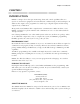
Chapter 7: Programming CHAPTER 7 ○ ○ ○ ○ ○ ○ ○ ○ ○ ○ ○ ○ ○ ○ ○ ○ ○ ○ ○ ○ ○ ○ ○ ○ ○ ○ ○ ○ ○ ○ ○ ○ ○ ○ ○ ○ ○ ○ ○ ○ ○ ○ ○ ○ ○ PROGRAMMING The standard parameter programming and system setup of ISACC is accomplished through using short command words called KEYWORDS and STAND ALONE commands. To use either type of command, you simply type the letters after an ISACC prompt (ISACC>) and then press the ENTER (or RETURN) key.
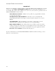
Sensaphone® ISACC Instruction Manual SYSTEM This keyword allows you access to the global system parameters, including: Unit identification - You may assign a name to the ISACC unit for identification. The name may be up to 31 numbers or characters long. Phone number of unit - The ISACC unit may be reached at this number. This number is used in voice mode identification. The phone number may be up to 31 digits long and can be typed plain, using hyphens and parentheses.
Chapter 7: Programming Online time out - When you are online with ISACC locally or remotely, the unit looks for inactivity. This parameter allows you to set the amount of time, 1 - 255 minutes, that ISACC will wait during inactivity before it terminates the online session, the default is 4 minutes. If there is inactivity that meets this parameter, ISACC will disconnect and display the message TIME OUT on your screen.
Sensaphone® ISACC Instruction Manual Voice alarm repetitions = 4 On line time out (minutes) = 4 Acknowledge on carrier = YES To change the global parameters, type set system after an ISACC prompt. Enter new information after the prompt (>).
Chapter 7: Programming To display the current input names, values, and status, type show inputs after an ISACC prompt: ISACC>show inputs INPUT IN01 = IN02 = IN03 = IN04 = IN05 = IN06 = IN07 = IN08 = IN09 = IN10 = IN11 = IN12 = IN13 = IN14 = IN15 = IN16 = NAME "Input "Input "Input "Input "Input "Input "Input "Input "Input "Input "Input "Input "Input "Input "Input "Input #1 #2 #3 #4 #5 #6 #7 #8 #9 #10 #11 #12 #13 #14 #15 #16 " " " " " " " " " " " " " " " " = = = = = = = = = = = = = = = = VALUE Open Open
Sensaphone® ISACC Instruction Manual IN14 is now Digital: N.O. IN15 is now Digital: N.O. IN16 is now Digital: N.O. Name = "Input #14 Name = "Input #15 Name = "Input #16 " " " To configure the input type and assign a descriptive name, type set itype after an ISACC prompt. Enter the type number to change the input type and press ENTER to get to the name parameter. Enter an input name. The name may be up to 16 characters. Press ENTER to go to the next input.
Chapter 7: Programming TABLE ISACC allows you to create up to four custom linear analog tables to be used with 4-20mA or 0-5V analog sensors. This allows you to translate a 4-20mA or 0-5V signal into a more meaningful number. For example, if your transducer is calibrated for 0-10' of water depth, an ITYPE of #3 (4-20mA) will express the water level as a percentage. However, using a table with a low of 0 and a high of 10, the water level will be expressed in feet.
Sensaphone® ISACC Instruction Manual LIMITS ISACC allows you to set high and low limits for inputs defined as 4-20mA analog, 0-5V analog, pulse count, temperature, table, or user defined. The limits are used to determine when an input is in alarm. The command SET LIMITS prompts you to enter these values. NOTE: An input defined as N.O. or N.C. does not have a high or low limit. ISACC will display N/A for that input. An input defined as pulse count can only have a high limit.
Chapter 7: Programming RECOGNITION The recognition time is the length of time that an alarm condition must exist continuously before ISACC will consider it a valid alarm and initiate a response. This keyword allows you to program the recognition time for each input. To display the currently programmed recognition times, type show recognition after an ISACC prompt. You may also display the recognition time for a specific input by typing show recognition followed by the input number.
Sensaphone® ISACC Instruction Manual ALARMS The keyword command SHOW ALARMS will display the present status of the inputs in alarm, if any alarms exist. The prefix SET is not valid with this keyword. To display the current input alarm status, type show alarms at an ISACC prompt: ISACC>show alarms DIALOUT ALARM STATUS No alarms DIALOUT This command allows you to enable or disable an input’s ability to cause a dialout during an alarm on that input.
Chapter 7: Programming IN10 IN11 IN12 IN13 IN14 IN15 IN16 = = = = = = = "Input "Input "Input "Input "Input "Input "Input #10 #11 #12 #13 #14 #15 #16 " " " " " " " = = = = = = = Yes Yes Yes Yes Yes Yes Yes (Y (Y (Y (Y (Y (Y (Y or or or or or or or N) N) N) N) N) N) N) >N > >N > > > > OUTPUTS ISACC has 8 digital outputs, 1 on-board relay, 1 on-board buzzer, 4 analog outputs. The outputs can be controlled manually, or can be controlled automatically by a C program.
Sensaphone® ISACC Instruction Manual OUT12 = "Analog output #2" = MAN, OUT13 = "Analog output #3" = MAN, OUT14 = "Analog output #4" = MAN, 000 > 000 > 000 > ONAME This keyword command allows you to assign a descriptive name to an output. To display the label name for each output, type the command show oname at an ISACC prompt. You may also display a specific output name by typing show oname followed by the output number.
Chapter 7: Programming PHONE ISACC is capable of dialing to up to 8 phone numbers, 32 digits each, during an alarm. ISACC can dial to a modem, to a standard touch-tone or pulse telephone (VOICE mode), to a beeper, or through an external modem. The command SET PHONE prompts you to program the phone number, the dialing mode (modem, voice, beeper, external modem), and a descriptive label name, a maximum of 16 characters, for each phone number.
Sensaphone® ISACC Instruction Manual 3 for Voice 4 for Beeper 5 for External Modem PH01, Num = Dialing mode PH02, Num = Dialing mode PH03, Num = Dialing mode PH04, Num = Dialing mode PH05, Num = Dialing mode PH06, Num = Dialing mode PH07, Num = Dialing mode PH08, Num = = (Voice = (Voice = (Voice = (Voice = (Voice = (Voice = (Voice Dialing mode = (Voice >14078546142b123456789**I ) >4 Name = "Phone #1 >16105551290 ) > Name = "Phone #2 >12035554044 ) > Name = "Phone #3 >12155559854 ) >1 Name = "Phone #4 >5
Chapter 7: Programming POUND OR ASTERISK: When dialing to a beeper, a pound sign (#) or an asterisk (*) may be used within the phone number. When using pulse dialing, the # or * will instruct ISACC to switch to tones for the remaining digits. Example: 1 # 6105554591 A P 986033 # NOTE: When dialing to a beeper it is sometimes necessary to combine codes. Certain beeper systems vary and you must adjust accordingly.
Sensaphone® ISACC Instruction Manual VOICE This keyword command allows you to select the input and output status information to be recited when you call into the unit for a status report using a standard telephone.
Chapter 7: Programming IN12 = "Input #12 " IN13 = "Input #13 " IN14 = "Input #14 " IN15 = "Input #15 " IN16 = "Input #16 " OUT01 = "WATER PUMP RELAY" OUT02 = "LOW WELL LIGHT " OUT03 = "HI SUMP LIGHT " OUT04 = "Output #4 " OUT05 = "Output #5 " OUT06 = "Output #6 " OUT07 = "Output #7 " OUT08 = "Output #8 " OUT09 = "On board buzzer " OUT10 = "On board relay " OUT11 = "CONTROL VALVE " OUT12 = "Analog output #2" OUT13 = "Analog output #3" OUT14 = "Analog output #4" = = = = = = = = = = = = = = = = = = = Yes Ye
Sensaphone® ISACC Instruction Manual NETWORK ISACC can communicate with other ISACC units without telephone lines through a network. After the network is set up, you must tell each ISACC unit the information it will have access to from another unit. See Chapter 3, for information on setting up the network. This predetermined information exchange is called an Information Network Request. The keyword command SET NETWORK allows you to program an Information Network Request.
Chapter 7: Programming VARIABLES ISACC allows you control over the information calculated in your C program. With the keyword command SET VARIABLES, you can set or alter the present value of any variable in your program.
Sensaphone® ISACC Instruction Manual STAND ALONE COMMANDS The STAND ALONE commands are used without the command prefix SET or SHOW to execute an action. The STAND ALONE commands are: RESET EXIT CLEAR DATA PATCH 123 HELP DIAG The format for using a STAND ALONE command is the following: ISACC>(COMMAND) RESET ISACC keeps track of all the highest and lowest events for each analog input. These are labelled MIN and MAX values.
Chapter 7: Programming PATCH This command enables you to communicate directly with an external device connected to the RS232 port when you call ISACC using a modem. This command also allows you to establish an online session with an ISACC unit not connected to your PC, but through the Master unit. This is called network patching.
Sensaphone® ISACC Instruction Manual EXIT This command “logs” you off from an online data programming or status inquiry session with ISACC. If you do not log off the unit cannot communicate until the online timeout expires. It will block alarm dialout! To log off ISACC, type exit after an ISACC prompt. ISACC>exit DATA This command displays input values from data log records for all or specified inputs. There are three parts to the DATA command. The first is the command itself.
Chapter 7: Programming DIAG This command runs a diagnostics test to verify system functioning and pinpoint errors. To run the diagnostics test, type diag following an ISACC prompt. ISACC>diag Crystal = 14.7456Mhz Board rev = C/D/E Software version = 3.
Sensaphone® ISACC Instruction Manual 76
Chapter 8: C Programming CHAPTER 8 ○ ○ ○ ○ ○ ○ ○ ○ ○ ○ ○ ○ ○ ○ ○ ○ ○ ○ ○ ○ ○ ○ ○ ○ ○ ○ ○ ○ ○ ○ ○ ○ ○ ○ ○ ○ ○ ○ ○ ○ ○ ○ ○ ○ ○ C PROGRAMMING Resident within ISACC is a C compiler . The purpose of putting a C compiler within ISACC is to offer remote programmability and flexibility. With a C program running, ISACC can perform logical input and output control and computation. SPECIFICATIONS The maximum size of your program can be 2K of compiled space, 8191 characters, or 500 lines, whichever comes first .
Sensaphone® ISACC Instruction Manual STAND ALONE COMMANDS: These are one word commands that are basic to the execution of a C program. These commands allow you to compile, test, start and stop a C program. KEYWORDS: These are short words or symbols that define variables or execute specific actions within a C program. They include operators, assignment, comparators, and comments.
Chapter 8: C Programming STRUCTURE Below are some examples that will help demonstrate the C language structure. Refer to following pages for explanation of the keywords, functions, and commands used within the sample programs. 1. All programs must begin with the main() function. It must be followed by an open brace { and closed with an end brace }. This program is valid, but will do nothing. main() { } 2. A statement is a line of programming code.
Sensaphone® ISACC Instruction Manual In many of the examples in this chapter, we use x and y as variable names. The variable name can be up to 15 characters long. Numbers can also be used as long as the name does not begin with a number. In addition to letters and numbers, the underscore character may be used in a variable name, but it cannot be the first character of the variable name.
Chapter 8: C Programming Example: In the following program, if x is greater than 30, the words “X is big” will print. If x is not greater than 30, the words “X is small” will print. In either case, “All done” will always print. int x; main() { x=23; if (x>30) { puts(“X is big\n”); } else { puts(“X is small\n”); } puts(“All done\n”); } There are C commands other than “if ” and “else”, and built in variables to access ISACC’s inputs and outputs. Details for these will be covered later.
Sensaphone® ISACC Instruction Manual EDITING COMMANDS The commands used to edit your program are INSERT, DELETE, ERASE and LIST. These commands allow you to insert and delete lines within a new or already existing program. When an existing line needs to be modified, the DELETE command is used to erase that line and the INSERT command is used to retype the line. The ERASE command eliminates an entire C program at once. The LIST command allows you to view the program on the screen.
Chapter 8: C Programming DELETE The DELETE command will let you delete a specific line or number of lines of your program. To delete a specific line of your program, type DELETE followed by the line number. For example: ISACC>delete 3 DELETE LINES ISACC> The text on line 4, if any, will be moved up to line 3. If you would like to delete a section of program, for instance lines 12 through 35, type DELETE, spacebar, 12, spacebar, 35.
Sensaphone® ISACC Instruction Manual STAND ALONE COMMANDS Stand alone commands are one word commands that are typed at an ISACC prompt. They are instructions for the physical execution of a C program. They allow you translate the C program into ISACC’s language, run the program once to test, start and stop the continuous execution of the program within ISACC. The four commands are COMPILE, RUN, START and STOP. COMPILE This command must be typed in before the program is executed.
Chapter 8: C Programming The reload time is how much time ISACC will wait between running the program. This is programmable so you can make the unit most efficient by telling ISACC to execute the C program only when necessary. For instance, if you require the program to run every half hour, it is not necessary to waste ISACC’s time and have the program run every 10 seconds. The reload time must be at least double the Run time and can be given in whole numbers only.
Sensaphone® ISACC Instruction Manual C LANGUAGE KEYWORDS The following is a list of all valid components of the C language within ISACC. char int if else for do while operators assignment comparators comments functions CHAR - used to define a variable as a character. A character can hold a value from -128 to +127 and must be a whole number. Exceeding this range will cause incorrect results. Example: char x; main() { x = 12; } INT - used to define a variable as an integer.
Chapter 8: C Programming ELSE - Used with IF to execute a statement when the IF condition is false. Example: main() { if (input(2)>100) { puts(“It is hot\n”); } else { puts(“It is cold\n”); } } FOR - Used to execute a statement (or statements) multiple times. Contains a start condition, a stop condition, and a control statement. The following example starts a counter at one, checks that it is less than nine, and executes the output statement.
Sensaphone® ISACC Instruction Manual OPERATORS - Symbols used to execute mathematical operations and determine whether a particular condition exists. + Adds two values. Subtracts two values. * Multiplies two values. / Divides two values. Produces a whole number result. % Finds the remainder of a division. || Checks if one condition or another exists. && Checks if one condition and another exists. ASSIGNMENT - Symbol used to assign a numeric value. = Assigns a new value to a variable.
Chapter 8: C Programming PREDEFINED VARIABLES ISACC’s C language has a number of variables that are predefined. These variables are automatically updated with the proper information outside of the C program and cannot be userchanged. They include: MONTH EXISTS DAY UPTIME YEAR HOURS MINUTES SECONDS MONTH, DAY, YEAR, HOURS, MINUTES & SECONDS These variables represent the values from the real time clock. They are defined as integer type.
Sensaphone® ISACC Instruction Manual Example: This program will turn on the buzzer (output 9) whenever any alarm occurs. It will turn the buzzer off when the alarm is acknowledged. main() { if (exists==1) { output(9,1); } else { output(9,0); } } UPTIME - This variable contains the number of seconds since the last power up or reset. This value starts at zero when the unit is powered up or reset, and will increase in increments of one up to 3600 seconds.
Chapter 8: C Programming FUNCTION LIBRARY In ISACC’s C language, there are a number of functions that are predefined. These functions allow you to retrieve certain values and incorporate them into your C program. A function can be a statement by itself or it can be used to retrieve a value and return it.
Sensaphone® ISACC Instruction Manual ALARM Summary: int alarm(n); int n; Input Number Description: The alarm function generates an alarm condition for the input specified by n. Return value: The alarm function always returns a zero. Example: This program will initiate an alarm 3 condition if input 3 is greater than 100 and input 2 is greater than 90.
Chapter 8: C Programming ENABLE Summary: int enable(n1,n2); int n1; Input number int n2; Command, 0=disable, 1=enable, 2=return status Description: The enable function enables, disables, or reads the dialout ability for an input specified by n1. Return value: The enable function returns 0 if the input is disabled, or a 1 if the input is enabled for dialout. Example: This program will disable dialout for input 4 from 12 noon to 12:59, and enable dialout for all other hours.
Sensaphone® ISACC Instruction Manual INPUT Summary: int input(n); int n; Input number Description: The input function will return the present value of an input specified by n1. When n1 is a number from 1 to 16, the return value is from the corresponding input. For n1 equals 17 to 20, the return values are the following: 17 18 19 20 The built in temperature sensor in degrees F. The built in temperature sensor in degrees C. Battery backup level in volts DC. AC power, 1 = on, 0 = off.
Chapter 8: C Programming IS_ALARM Summary: int is_alarm(n); int n; Input number Description: The is_alarm function checks if there is an active dialout alarm on the input specified by n. This follows the unacknowledged status on the alarm, so after the alarm is acknowledged by someone, it is no longer considered an alarm even if the physical condition is still there. Return value: The is_alarm function returns a zero if there in no alarm on input n, or a 1 if there is an alarm.
Sensaphone® ISACC Instruction Manual NETWORK Summary: int network(n1,n2); int n1; Request number int n2; Command, 0=turn off, 1=turn on, 2=return status Description: The network function will read a value or write a value to one of the predetermined network requests (specified by n1). If the network request is an output function, then the value of n2 is the value sent to that output. If the network request is an input function, then n2 should have the value 2.
Chapter 8: C Programming OUTPUT Summary: int output(n1,n2); int n1; Output number int n2; Command, 0=turn off;1=turn on;2=return status Description: The output function will turn a digital output specified by n1 on or off, or will just read the present state of the output. It will also set the value of an analog output. The analog outputs, referred to as outputs 11 through 14, are 0 to 10V. They are specified by 8 bit data from 0 to 255.
Sensaphone® ISACC Instruction Manual OUT_SPEC Summary: int out_spec(n); int n; Input number Description: The out_spec function checks if the value of input n is outside of the high and low alarm limits. This is without regard to alarm processing, recognition time, acknowledged status, dialout selection, and dialout enabling. Return value: The out_spec function will return a zero if the input is within limits, and will return a nonzero result if it is outside of the limits.
Chapter 8: C Programming PUTS Summary: int puts(s); char * s; String Description: The puts function will write a string to the local RS232 port. Return value: The puts function always returns a zero. Example: This program will send the string “SHUTDOWN” followed by a carriage return, and send the string “Input 11 is 96” followed by a carriage return to the RS232 port when input 11 is equal to 96. A carriage return is created by typing \n.
Sensaphone® ISACC Instruction Manual RESET Summary: int reset(n); int n; Input number Description: The reset function resets the values automatically maintained by the system for an input specified by n. If the input is analog, reset resets the max and min values. If the input is a pulse counter, reset sets the pulse count to zero. If the input is a dry contact, reset has no effect. Return value: The reset function always returns a zero.
Chapter 8: C Programming RELOAD Summary: int reload(); Description: The reload function returns the reload rate in seconds of the C program. There are no parameters. Return value: The reload rate in seconds of the C program. Example: This program will use the reload rate to update a seconds down-timer. When the timer hits zero, it will turn output number 1 on.
Sensaphone® ISACC Instruction Manual SET_INPUT Summary: int set_input(n1,n2); int n1; Input number int n2; New value of input Description: The set_input function will allow you to manually set the input value for any of the 16 input channels. This is useful to get a average or some other calculated value to appear on an input channel. That value is then treated as any other analog input for alarm functionality and also appears in the data logger.
Chapter 8: C Programming ARRAYS Arrays allow you to store a lot of related information in a convenient, organized fashion. An array lets you use one line of code to create a series of variables. These variables share the same basic name and are distinguished from one another by a numerical tag. Example: int count[10]; This means that an array named count has 10 members or “elements,” with each element having its own value, starting with 0 and ending with 9.
Sensaphone® ISACC Instruction Manual The following is a step by step explanation of the program. 1. if (oldminute != minutes) { oldminute = minutes; This checks the value of minutes to see if a minute has passed. If a minute has passed, the value of oldminute is reset to the value of the new minute. 2. numbers[minutes] = input(1); This line sets the value of numbers for a particular minute to the current value of input 1. For example: It is 3 minutes into the hour. The value of input 1 is 72°.
Chapter 8: C Programming 6. When x reaches 60, the For loop is finished, and the average is calculated. average = total/60; 7. ISACC automatically rounds numbers down. This section of code rounds the value of average up to the next whole number according to the remainder left over during division. If the remainder is greater than 30, average is rounded up. if ((total % 60) >= 30) { average = average + 1; 8. This line sets the value of input 2 to the hourly average just calculated.
Sensaphone® ISACC Instruction Manual ERROR HANDLING When a program is compiled, it is scanned for language related errors. When an error is encountered, the word ERROR is displayed followed by the error type, and line number. The line number may not be the exact line that contains the error. Sometimes an error is detected a line or two after the actual mistake. If an error occurs while compiling, the compiler aborts.
Chapter 8: C Programming DIFFERENCES BETWEEN STANDARD C AND ISACC C For those of you who are familiar with C programming, note that there are some differences between standard C and ISACC’s C compiler. The following items will be helpful to be aware of: 1. With ISACC C, every IF, ELSE, FOR, DO, and WHILE must have a set of brackets {} after it. 2. Condition clauses must be grouped together into pairs.
Sensaphone® ISACC Instruction Manual The first program fragment uses a WHILE loop for the timing. if (input(1)==0) { output(9,1); start_time=minutes; while ((start_time+1)>minutes) { } output(9,0); } if (input(2)==0) { data (0,0,1,1); } In this code fragment, when input 1 closes, the program will turn output 9 on, and then wait for 60 seconds without doing anything else. Input 2 may close during this time period, and critical data may be lost.
Chapter 8: C Programming PROGRAMMING EXAMPLES 1.
Sensaphone® ISACC Instruction Manual recent = input(1); /* Get the value from input 1 */ if ((hours==6)&&(prvhrs!=6)) /* This segment of code runs only when the hours change to */ { /* 6 o’clock */ total = total + recent; average = total / 24; prvhrs=hours; /* This prevents the previous IF statement from executing */ } /* more than once during the hour of 6 o’clock */ } 4. This example shows: PUSH BUTTON RESET and SINGLE ALARM FOR POWER OUTAGE.
Chapter 8: C Programming 5. This example demonstrates usage of the DATA LOGGER from within a C program. This program will run the data logger when an input is alarmed.
Sensaphone® ISACC Instruction Manual COMMON ISACC PROGRAMMING ERRORS As you develop ISACC programs, you may find that your programs do not work as you intended. The following programs show common programming errors. 1. Program does not turn on the buzzer main() { output(9,1); } Usually, this is because the output needs to be set on AUTO. Use keyword command SET OUTPUT 9, and set it for AUTO in the standard programming parameters. 2.
Chapter 8: C Programming 3. This program simply does not do what it should: int x; main() { x=input(5); if (x=10) { output(9,1); } else { output(9,0); } } The problem is that the statement: if (x=10) actually assigns the value of 10 to x. The key is that it uses a single equals sign ‘=’. To test a condition, use the double equals sign, ‘==’.
Sensaphone® ISACC Instruction Manual 114
Chapter 9: Operation CHAPTER 9 ○ ○ ○ ○ ○ ○ ○ ○ ○ ○ ○ ○ ○ ○ ○ ○ ○ ○ ○ ○ ○ ○ ○ ○ ○ ○ ○ ○ ○ ○ ○ ○ ○ ○ ○ ○ ○ ○ ○ ○ ○ ○ ○ ○ ○ OPERATION HOW THE UNIT WORKS ISACC monitors up to 16 universal inputs. When the status of an input changes or exceeds user-programmed limits, it causes an alarm.
Sensaphone® ISACC Instruction Manual The alarm has been acknowledged and the unit will then disconnect from the telephone line. If the touch-tone code is not received, ISACC will respond by saying: "Have a good day." The alarm is not acknowledged. ISACC will continue calling the next phone number. You may call the unit back using a touch-tone telephone, PC or terminal to acknowledge the alarm. An alarm cannot be acknowledged using a pulse (rotary) telephone.
Chapter 9: Operation ALARM DIALOUT - BEEPER When dialing to a beeper, you can program ISACC to send digits that identify itself and the input in alarm. See Chapter 7, Dialing Codes. You must acknowledge the alarm by calling the unit back using a touch-tone telephone, PC or terminal. CALL PROGRESS VOICE OR BEEPER MODE: ISACC monitors call progress when dialing out in voice or beeper mode.
Sensaphone® ISACC Instruction Manual VOICE MODE OUTPUT CONTROL Following the voice status report, ISACC allows you to turn on or off one of the digital outputs (1-10) using a touch-tone telephone. At the end of the report, you have 5 seconds to enter a touch-tone command. To switch an output: 1. Using the touch-tone phone keypad, enter the number of the output you want to manipulate (1, 2, 3, 4 ,5, 6, 7, 8, 9, or 0 for 10) within 5 seconds. 2. To turn the output on, press 1. 3.
Chapter 9: Operation also have an error-checking modem for your PC or terminal. To install the external modem: 1. Power up and set the modem according to the manufacturer's instructions. 2. Connect the external modem to ISACC's RS232 serial port. 3. Connect the phone line. This can be done one of two ways: a. Hook up the phone line directly to the external modem. If you do this, you cannot use dialing modes 0-4 (see Chapter 7). Also, you cannot call into ISACC for a voice mode status report.
Sensaphone® ISACC Instruction Manual 120
Chapter 10: Glossary CHAPTER 10 ○ ○ ○ ○ ○ ○ ○ ○ ○ ○ ○ ○ ○ ○ ○ ○ ○ ○ ○ ○ ○ ○ ○ ○ ○ ○ ○ ○ ○ ○ ○ ○ ○ ○ ○ ○ ○ ○ ○ ○ ○ ○ ○ ○ ○ GLOSSARY STAND-ALONE COMMANDS Clear - Used alone or with an input number to stop the dial out for a specific alarm. Compile - Instructs ISACC to compile your C program. Data - Instructs ISACC to display the records of the data logging function. Delete - Allows deletion of one or more lines of your C program. Diag - Runs a diagnostics test to help pinpoint functioning errors.
Sensaphone® ISACC Instruction Manual SET/SHOW KEYWORDS Alarms - Used with show to display any outstanding alarms. Clock - Battery-backed clock that allows the time and date to be displayed or programmed. Dialout - Used to display or instruct ISACC to enable or disable the dialout for each alarm. Inputs - Used with show to display the present values of the inputs. If an input number is followed, the command only displays that specific input.
Appendix A: Proper Operation APPENDIX A ○ ○ ○ ○ ○ ○ ○ ○ ○ ○ ○ ○ ○ ○ ○ ○ ○ ○ ○ ○ ○ ○ ○ ○ ○ ○ ○ ○ ○ ○ ○ ○ ○ ○ ○ ○ ○ ○ ○ ○ ○ ○ ○ ○ ○ CHECKING YOUR SENSAPHONE FOR PROPER OPERATION We recommend that you test your Sensaphone weekly to be sure it is functioning properly. This will ensure that when a problem arises the Sensaphone will be ready to alert the appropriate personnel. There are several tests that can be performed: 1) Call the unit and listen to the Status Report.
Sensaphone® ISACC Instruction Manual 124
Appendix B: Engineering Specifications APPENDIX B ○ ○ ○ ○ ○ ○ ○ ○ ○ ○ ○ ○ ○ ○ ○ ○ ○ ○ ○ ○ ○ ○ ○ ○ ○ ○ ○ ○ ○ ○ ○ ○ ○ ○ ○ ○ ○ ○ ○ ○ ○ ○ ○ ○ ○ ENGINEERING SPECIFICATIONS I. General The Automatic dialer shall be a self-contained microprocessor controlled system capable of monitoring and controlling up to 16 alarm channels. The system shall be integrated in construction and shall be installed and configured for operation by the user via keyword command programming on a data terminal or PC.
Sensaphone® ISACC Instruction Manual II. I/O Channel Attributes and Features A. Inputs The system shall come standard with 16 universal input channels. All input channels shall be user-configurable as: 1. 2. 3. 4. 5.
Appendix B: Engineering Specifications The system shall be capable of dialing up to 8 telephone numbers, 32 digits each. Individual Dialout Alarm Selection may be programmed for each input channel to instruct the system to dial specific telephone numbers for certain alarms. The system shall allow local or remote data programming of the following telephone dialing information: 1. 2. 3. 4. 5. 6. 7. 8.
Sensaphone® ISACC Instruction Manual remotely by terminal or PC. C. Diagnostics and Testing The system shall have built-in diagnostic tests to pinpoint system problems. D. Security The system shall allow the user to program a data password to prevent unauthorized local or remote access to programming. VI. Remote Operation Features A.
Appendix B: Engineering Specifications D. Electrical Protection Power and telephone connection shall have internal spike and surge protection using metal oxide varistors. All input channels shall have spike protection and noise filter circuits. E. Additional Electrical Surge Protection Additional Power and Telephone line surge protection shall be available from the manufacturer.
Sensaphone® ISACC Instruction Manual 130
Appendix C: Board Layout APPENDIX C ○ ○ ○ ○ ○ ○ ○ ○ ○ ○ ○ ○ ○ ○ ○ ○ ○ ○ ○ ○ ○ ○ ○ ○ ○ ○ ○ ○ ○ ○ ○ ○ ○ ○ ○ ○ ○ ○ ○ ○ ○ ○ ○ ○ ○ BOARD LAYOUT Optional analog output terminal block Digital output terminal block EG 24 24 BAT C 20V C AC AC 15V C 12V C 5 V C 8 7 6 5 4 3 2 1 C C 12V C 5V 4 C 3 C 2 C 1 NC COM NO On-board relay output terminal block Power supply terminal block RELAY DIGITAL OUTPUTS ANALOG OUTPUTS ON P10 Communications speed configuration pins OFF 1 2 3 P11 NC RECHARGE
Sensaphone® ISACC Instruction Manual 132
Appendix D: Mounting I/O Devices APPENDIX D ○ ○ ○ ○ ○ ○ ○ ○ ○ ○ ○ ○ ○ ○ ○ ○ ○ ○ ○ ○ ○ ○ ○ ○ ○ ○ ○ ○ ○ ○ ○ ○ ○ ○ ○ ○ ○ ○ ○ ○ ○ ○ ○ ○ ○ MOUNTING I/O DEVICES This appendix includes diagrams to show you how various combinations of I/O racks and relays mount into the ISACC enclosure.
Sensaphone® ISACC Instruction Manual Steel back plate Mounting holes for high power relays Mounting holes for 4-module rack and 8-module rack EG 24 24 BAT C 20V C AC AC 15V C 12V C 5V C 8 7 6 5 4 3 2 1 C 12V C 5V C 4 C 3 C 2 C 1 NC COM NO ISACC circuit board ANALOG OUTPUTS OFF ON ON P10 1 2 3 P11 NC DIGITAL OUTPUTS P14 RECHARGE RELAY POWER OFF Pre-drilled holes in ISACC steel panel 134
One 4-module rack mounted to steel panel OFF ON ON 1 2 3 P11 OFF P10 NC RECHARGE P14 POWER DIGITAL OUTPUTS ANALOG OUTPUTS RELAY ISACC circuit board EG 24 24 BAT C 20V C AC AC 15V C 12V C 5V C 8 7 6 5 4 3 2 1 C 12V C 5V C 4 C 3 C 2 C 1 NC COM NO 2I0-4A 9 8 7 6 5 4 3 2 1 9 8 7 6 5 4 3 2 1 4-module rack Steel back plate Appendix D: Mounting I/O Devices
One 8-module rack mounted to steel panel OFF ON ON 1 2 3 P11 OFF P10 NC RECHARGE P14 POWER DIGITAL OUTPUTS ANALOG OUTPUTS RELAY ISACC circuit board EG 24 24 BAT C 20V C AC AC 15V C 12V C 5V C 8 7 6 5 4 3 2 1 C 12V C 5V C 4 C 3 C 2 C 1 NC COM NO 2IO-8 0 1 2 3 4 5 6 7 1 8-module rack 1 6 1 5 1 4 1 3 1 2 11 1 0 9 8 7 6 5 4 3 2 1 25 Steel back plate Sensaphone® ISACC Instruction Manual
Appendix D: Mounting I/O Devices 1 2 1 2 1 2 1 2 4 + 3 4 + 3 4 + 3 4 + 3 Steel back plate High power relays 1 1 2 2 1 2 1 2 Mounting holes for 4-module rack and 8-module rack 4 + 3 8 7 6 5 + 3 4 15V C 12V C 5V C 4 3 2 1 4 C 12V C 5V C 4 C + 3 + 3 EG 24 24 BAT C 20V C AC AC 3 C 2 C 4 1 NC COM NO ISACC circuit board NC P11 ANALOG OUTPUTS P14 DIGITAL OUTPUTS OFF ON ON P10 1 2 3 RECHARGE RELAY POWER OFF 8 high power solid state relays mounted to
Sensaphone® ISACC Instruction Manual 2 1 2 4 + 3 4 + 3 Steel back plate 9 8 7 6 5 4 3 2 1 1 4-module rack 1 2 4 + 3 4 + 3 2I0-4A 2 9 8 7 6 5 4 3 2 1 1 High power relays EG 24 24 BAT C 20V C AC AC 15V C 12V C 5V C 8 7 6 5 4 3 2 1 C 12V C 5V C 4 C 3 C 2 C 1 NC COM NO ISACC circuit board NC P11 ANALOG OUTPUTS P14 DIGITAL OUTPUTS OFF ON ON P10 1 2 3 RECHARGE RELAY POWER OFF 4 high power solid state relays and one 4-module rack mounted to steel panel 138
Appendix E: Accessories APPENDIX E ○ ○ ○ ○ ○ ○ ○ ○ ○ ○ ○ ○ ○ ○ ○ ○ ○ ○ ○ ○ ○ ○ ○ ○ ○ ○ ○ ○ ○ ○ ○ ○ ○ ○ ○ ○ ○ ○ ○ ○ ○ ○ ○ ○ ○ ACCESSORIES The sensors and accessories listed below are the most commonly used with ISACC. In addition, there are a virtually unlimited variety of sensor/switch input devices available at commercial or industrial electrical supply houses. They can provide a device to monitor virtually any condition that might be required for your business, industrial or residential needs.
Sensaphone® ISACC Instruction Manual 140
Appendix F: Return for Repair APPENDIX F ○ ○ ○ ○ ○ ○ ○ ○ ○ ○ ○ ○ ○ ○ ○ ○ ○ ○ ○ ○ ○ ○ ○ ○ ○ ○ ○ ○ ○ ○ ○ ○ ○ ○ ○ ○ ○ ○ ○ ○ ○ ○ ○ ○ ○ RETURN FOR REPAIR In the event that ISACC does not function properly and you cannot reprogram it, we suggest that you do the following: 1) Carefully write down your observations of ISACC's malfunctioning. 2) Call Phonetics' Technical Service at (610) 558-2700 if any instructions are not clear or if you have any question.
Sensaphone® ISACC Instruction Manual 142
WARRANTY 1 YEAR LIMITED WARRANTY 1. WARRANTOR: Dealer, Distributor, Manufacturer 2. ELEMENTS OF WARRANTY: This Product is warranted to be free from defects in materials and craftsmanship with only the limitations and exclusions set out below. 3.