
User Manual


6
AM844D USB
English Deutsch Español Français Português
日本語
简体中文
44. AUX Send Solo Buttons
Push these buttons to send the signals from the corresponding
AUX Sends mixes to the Control Room / Phones mix. The AUX
3 mix will be sent to the left of the Control Room / Phones stereo
mix, while the AUX 4 will be sent to the right.
45. Solo Control
When one or more solo buttons are activated on any channel, this
control adjusts the signals’ levels before sending the amplified
signal to the Control Room / Phones mixing bus. This enables
the user to be able to switch between monitoring the Main L-R (or
other selected signals) and the solo signals without being over-
whelmed by the difference in signal levels.
46. 2T / USB Return Controls
Turning the 2T Return level control adjusts the signal level of
the feed from the 2T Return inputs, as well as the return signal
from the computer through the USB interface. The “To Main L-R”
button that accompanies this control allows users to send the 2T/
USB return signal to the Main stereo mix. When this is done, the
return signal is not sent to the Record Out, as to avoid producing
a feedback loop when recorded signals are fed back into the 2T
return.
47. Control Room / Phones Controls
These two controls are used to adjust the audio level of the
Control Room and Phones feeds, for use in the monitoring and
tracking of audio. The Control Room control adjusts the final level
sent to the C-R outputs on the rear of the AM844D USB mixer,
whereas the Phones control adjusts the final signal sent to the
Phones A and B jacks on the top of the mixer’s face.
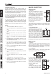
48. Control Room / Phones Source Selection
These four buttons allow users to select the various possible
sources for the Control Room and Phones outputs. By simply
pushing one of these buttons, users have the ability to monitor
the Group 1-2, Group 3-4, Main L-R and 2T Return (by the Ctrl
Rm / Phones only button) signals, either together or individually.
Priority Signal
High From Solo
Low Selected Source(s)
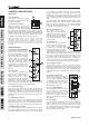
49. +48V Indicator
This indicator will illuminate when Phantom Power is activated.
50. Power Indicator
The Power Indicator will light up when the power of the mixer is
on; in case you weren’t too sure.
51. Level Meter
This dual 12 segment level meter gives an accurate indication
of when audio levels of the Main L/R signal reach certain levels.
The 0 dB indicator illuminates is approximately equal to an output
level of +4 dBu (balanced), and the PEAK indicator illuminates
about 1.5 dB before the signal is dynamically clipped. To make
the maximum use of audio, set the various level controls so that
it sits steadily around 0 dB to make full use of audio, while still
maintaining fantastic clarity.
When the Solo indicator, located beside the Level Meter, is
illuminated, one or more Solo buttons has been pushed; therefore
the Level meter will display properties of the Solo signal, which
is helpful with setting of channel properties. If Solo indicator
illuminates green, this means the Solo feed is a pre-fader signal.
If the solo indicator illuminates red, the feed is post-fader. If no
Solo buttons are activated, the Control Room / Phones selected
sources (Main L-R, Group 1-2, Group 3-4 and/or 2T Return)
signal properties are displayed by the Level Meter. In this case,
the Level meter will display the sum of the selected signals.
52. Group 1/5, 2/6, 3/7 and 4/8 Controls
These four faders are the final level control for the Group 1 to
4 audio feeds (the signals of which are doubled in the 5 – 8
Group outputs), sent to the corresponding Group outputs on
the rear of the AM844D USB to feed external devices such as
effect processors, and, most commonly, multi-track recorders.
These faders can be fed a signal from the various mono and
stereo channels, as well as the AUX Return 3, depending on your
selections. When pushed all the way up, these faders provide
10 dB of gain to the signal, and, when set all the way down,
effectively mute the signal.
The Group Controls also feature individual left and right buttons,
which allow you to send the various Group signals to the Main
Left and Right. This can be handy when wanting to combine
the signals from different signals and control their input levels
simultaneously, then send them to the Main L/R signal (eg. When
multiple inputs are used for drums, you can combine these inputs
together to be controlled much simpler by a single fader).
53. Main Fader
This fader is the final level control for the Main Left and Right
audio feeds, sent to the Main L and R outputs. When pushed
all the way up, the Main L/R fader provides 10 dB of gain to the
signal, and when set all the way down, the signal is effectively
muted. This will also adjust the final output level of the signal sent
through the USB interface to the computer.
46
45
47
48
49 50
51
52
53