
User Manual


3
AM844D USB
English Deutsch Español Français Português
日本語
简体中文
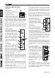
Rear Panel
8. Direct Outs
These connections are for the direct output of the signals
received by mono channels 1 through to 8, post-fader, post-EQ,
post-HPF, post-mute. They are most commonly used to connect
Multi-track recorders, allowing the AM844D USB to be used as
an 8-track studio mixer.
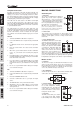
9. Insert Jacks
The primary use for these TRS
phone jacks is for the addition
of external devices, such as
dynamic processors or equalizers,
to the corresponding mono input
channel. This will require a Y cord
that can send and receive signals
of the mixer to and from an external
processor.
10. Auxiliary (AUX) Sends
These 1/4” phone jacks are the final output of line-level signal
fed from the corresponding auxiliary send mixes, and are best
suited for use with stage monitors. Feeding the output from the
Auxiliary outs to an amplifier - and possibly an equalizer - and
then to a floor monitor speaker allows artists to monitor their own
instruments or vocals whilst performing.
11. Main Outputs
These outputs will output the final stereo line level signal sent
from the main mix. The primary purpose of the two XLR jacks is
to send the main output to external devices, which may include
power amplifiers (and in-turn, a pair of speakers), other mixers,
as well as a wide range of other possible signal processors
(equalizers, crossovers, etcetera). The two 1/4” phone jacks
are able to send the Main output to external devices that may
run in parallel with the mixer. This may include additional power
amplifiers, mixers, PA systems, as well as a wide range of other
possible signal processors.
12. Main Insert
Located on the rear of the AM844D USB, the primary use for
these TRS phone jacks is for the addition of external devices,
such as dynamic processors or equalizers, to the main L and
main R signals. This will require a Y-cable that can send (pre-
fader) and receive signals to and from an external processor.
13. Control Room Outputs
These two 1/4” phone jack outputs
feed the signal altered by the
Control Room level control on the
face of the mixer. This output has
extensive use, as it can be used to
feed the signal from the mixer to an
active monitor, for the monitoring of
the audio signal from within a booth,
among many other possible uses.
14. Foot Switch Jack
These ports are for the inclusion of a foot switch, used to remotely
change the built-in digital effect processor between on and off.
15. Group Outs
These 1/4” phone jacks output the final feed from the Group
1/5, 2/6, 3/7 and 4/8 Faders on the main panel of the mixer.
These outputs can be used to feed multi-track records, as well
as an amplifier and speakers to be used along with the Main
Speakers.
NB. When sending unbalanced signals from this output, a 1/4” TRS stereo
plugs must be used and have the ring-pin disconnected, as to avoid
damaging this mixer.
16. AUX Returns
The 1/4” TRS AUX Return inputs are for the return of audio to the
AM844D USB mixer, processed by an external signal processor.
If really needed, they can also be used as additional inputs. The
feed from these inputs can be adjusted using the AUX Return
controls on the face of the mixer. When connecting a monaural
device to the AUX Return 1, 2 and 4 inputs, simply plug a 1/4”
phone jack into the left (mono) input, and the signal will appear
in the right as well. This, however, does not work for the AUX
Return 3.
NB. When any device is plugged into the mixer’s corresponding EFX
Return inputs (AUX Return 3), the mixer’s internal digital effect engine is
then disabled.
17. USB Port
This USB connector can be used to connect the AM844D
USB to any modern Windows or Mac-based computer. Doing
so will allow users to get a stereo signal both to and from the
computer.
18. Power Connector and Fuse Holder
This port is for the addition of a power cable and supply, allowing
power to be supplied to the mixer. Please use the power cable
that is included with this mixer only. The fuse holder (located
above the AC Power connector) is for the AM844D USB’s fuse. If
the fuse happens to blow, open the holder cover, and replace the
fuse with a suitable replacement (as indicated below the power
connector).
9
8
10
11
12 13 14
15 16
17
18