LIFEPAK 20e DEFIBRILLATOR /MONITOR ® OPERATING INSTRUCTIONS
LIFEPAK 20e DEFIBRILLATOR /MONITOR ® OPERATING INSTRUCTIONS
Important Information !USA Rx Only !USA Device Tracking The U.S. Food and Drug Administration requires defibrillator manufacturers and distributors to track the location of their defibrillators. If the device is located somewhere other than the shipping address or the device has been sold, donated, lost, stolen, exported, destroyed, permanently retired from use, or if the device was not obtained directly from Physio-Control, please do one of the following: register the device at http://www.physio-control.
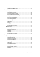
CONTENTS Preface About Automated External Defibrillation ...................................................................... viii About Defibrillation Therapy ..........................................................................................ix About Noninvasive Pacing ............................................................................................. x About SpO2 Monitoring .................................................................................................
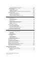
Battery Operation .......................................................................................................2-20 LIFEPAK 20e Defibrillator/Monitor Battery ..........................................................2-20 CodeManagement Module Battery ......................................................................2-23 3 Monitoring Monitoring the ECG......................................................................................................3-2 ECG Monitoring Warning................
Synchronized Cardioversion Procedure.............................................................. 4-18 Remote Synchronization Procedure.................................................................... 4-20 Pediatric Defibrillation ................................................................................................ 4-21 Pediatric Paddle Placement ................................................................................ 4-21 Defibrillation Procedure .....................................
Cleaning.................................................................................................................7-5 Function Checks ....................................................................................................7-5 General Troubleshooting Tips ...................................................................................7-10 Service and Repair.....................................................................................................
Preface PREFACE About Automated External Defibrillation About Defibrillation Therapy About Noninvasive Pacing About SpO2 Monitoring About ECG Monitoring About EtCO2 Monitoring LIFEPAK 20e Defibrillator/Monitor Operating Instructions ©2006-2013 Physio-Control, Inc.
Preface ABOUT AUTOMATED EXTERNAL DEFIBRILLATION The following considerations and guidelines apply when using the LIFEPAK® 20e defibrillator/ monitor as an automated external defibrillator (AED). Operator Considerations The LIFEPAK 20e defibrillator/monitor, when in AED mode, is a semiautomatic defibrillator that uses a patented Shock Advisory System™. This software algorithm analyzes the patient’s electrocardiographic (ECG) rhythm and indicates whether or not it detects a shockable rhythm.
Preface Preface ABOUT DEFIBRILLATION THERAPY Operator Considerations A direct current defibrillator applies a brief, intense pulse of electricity to the heart muscle. The LIFEPAK 20e defibrillator/monitor delivers this energy through disposable electrodes, standard paddles or internal paddles applied to the patient’s chest. Defibrillation is only one aspect of the medical care required to resuscitate a patient with a shockable ECG rhythm.
Preface ABOUT NONINVASIVE PACING A noninvasive pacemaker is a device that delivers an electrical stimulus to the heart, causing cardiac depolarization and myocardial contraction. The energy is delivered through large adhesive electrodes placed on the chest. In addition to noninvasive pacing, other supportive measures may be necessary. Among other factors, it is recognized that successful pacing of a patient is related to the length of time between the onset of a dysrhythmia and the initiation of pacing.
Preface Preface ABOUT ETCO2 MONITORING The end-tidal carbon dioxide (EtCO2) monitor is a capnograph device that uses non-dispersive infrared spectroscopy to continuously measure the amount of CO2 during each breath and report the amount present at the end of exhalation (EtCO2). The sample is obtained by the side stream method and can be used with intubated or nonintubated patients. Respiration rate is also measured and displayed in breaths per minute.
SAFETY INFORMATION 1 Safety Information This section provides important information to help you operate the LIFEPAK 20e defibrillator/ monitor. Familiarize yourself with all of these terms, warnings, and symbols. Terms General Warnings and Cautions Symbols LIFEPAK 20e Defibrillator/Monitor Operating Instructions ©2006-2013 Physio-Control, Inc.
Safety Information TERMS The following terms are used either in these operating instructions or on the LIFEPAK 20e defibrillator/monitor: Danger: Immediate hazards that will result in serious personal injury or death. Warning: Hazards or unsafe practices that may result in serious personal injury or death. Caution: Hazards or unsafe practices that may result in minor personal injury, product damage, or property damage. GENERAL WARNINGS AND CAUTIONS The following are general warning and caution statements.
Safety Information WARNINGS! (CONTINUED) Possible electrical interference. Using cables, electrodes, or accessories not specified for use with this device may result in increased emissions or decreased resistance to electromagnetic interference which could affect the performance of this device or of equipment in close proximity. Use only parts and accessories specified in these operating instructions. Possible electrical interference.
Safety Information SYMBOLS The symbols below may be found in these operating instructions or on various configurations of LIFEPAK 20e defibrillator/monitor and accessories: Defibrillation-proof type CF terminal Defibrillation protected, type BF patient connection Attention, consult accompanying documents Attention, consult accompanying documents. (Symbol has blue background and graphical symbol is white.) Warning, high voltage Type BF patient connection Static sensitive device (SSD) Safety ground.
Safety Information Indoor use only Alarm on Alarm off VF/VT alarm on VF/VT alarm silenced 1 Safety Information Greater than Less than J Joules Adult defibrillation paddle Infant defibrillation paddle Home screen button Battery status indicator (refer to page 2-21) Heart rate/pulse rate indicator (x) Shock count (x) on screen Mark of conformity to applicable European Directives Canadian Standards Association certification for Canada and the United States Recognized component mark for Canada and th
Safety Information AC voltage On (power: connection to the AC Mains) Off (power: disconnection from the AC Mains) Power on/off AC power indicator (CodeManagement Module only) [signal] Input [signal] Output CO2 Input CO2 Exhaust This end up Fragile/breakable Handle with care Protect from water Recommended storage temperature 5° to 45°C (41° to 113°F). Storage at extreme temperatures of -20° or 60°C (-4° or 140°F) is limited to seven days.
Safety Information Turn counterclockwise to unlock Switch on Switch off Pace arrow, noninvasive pacing Pace arrow, internal pacing 1 Safety Information R-wave sense marker Event marker Biphasic defibrillation shock Shock button !USA For USA audiences only IPx1 Protected from dripping water per IEC 60529 Serial number CAT Catalog number used for placing orders Manufacturer’s Identification Number (part number) Federal law restricts this device to sale by or on the order of a physician Manufact
BASIC ORIENTATION This section provides a basic orientation to the LIFEPAK 20e defibrillator/monitor. LIFEPAK 20e Defibrillator/Monitor Operating Instructions ©2006-2013 Physio-Control, Inc.
Basic Orientation INTRODUCTION The LIFEPAK 20e defibrillator/monitor with enhanced battery technology is an acute cardiac care response system used by authorized healthcare providers in hospital and clinic settings.
Basic Orientation Note the label located to the right of the screen (Figure 2-1). Before the defibrillator/monitor’s first use, plug the power cord into an AC outlet for 3 hours to charge the internal battery. Figure 2-1 Initial Battery Charge If you purchased the CodeManagement Module, you will need to connect it to the LIFEPAK 20e defibrillator/monitor. Refer to the Installation Instructions provided with the CodeManagement Module for more information.
Basic Orientation The door on the LIFEPAK 20e defibrillator/monitor hides the manual defibrillation and noninvasive pacing buttons. When the door is closed, the appearance and operation of the device is simplified for the automated external defibrillator (AED) user. To enter manual mode, press the MANUAL button located on the lower left corner of the door. This opens the door and automatically takes the device out of AED mode and allows access to manual mode defibrillation and pacing.
Basic Orientation Area 1 Adult Ventricular Fibrillation Energy Label Refer to page F-2. 1 ON Switches power on or off. Recommended Adult VF Dose: xxx-xxx-xxxJ AED MODE LED illuminates when AED mode is active. Refer to page 4-5. ANALYZE Activates Shock Advisory System (SAS). Refer to page 4-7. ENERGY SELECT Selects energy levels in manual mode. Refer to page 4-14. CHARGE Charges the defibrillator in manual mode. Refer to page 4-14. SHOCK Discharges defibrillator energy to the patient.
Basic Orientation Area 3 3 EVENT Activates userdefined events. Refer to page 2-6. LEAD Changes ECG lead. Refer to page 3-2. HOME SCREEN Returns immediately to Home Screen. Refer to page 2-6. SIZE Changes ECG size. Refer to page 3-2. ALARMS Activates and silences alarms. Refer to page 2-17. LED Illuminates when the Speed Dial is active. Refer to page 2-8. OPTIONS Accesses optional functions. Refer to page 2-7.
Basic Orientation Options After pressing OPTIONS, the screen displays the overlay shown in Figure 2-7. Use the Speed Dial to scroll through and select menu choices. PATIENT Enters patient name, patient ID, location, age, and sex. PACING Selects demand or nondemand pacing. Selects internal pacer detection on/off. DATE/TIME Sets the date and time. For changes to take effect, cycle power. ALARM VOLUME Adjusts volume for alarms, tones, and voice prompts.
Basic Orientation Area 4 The following paragraphs provide additional information about the Speed Dial and the therapy cable connector shown in Area 4. Speed Dial Use the Speed Dial to scroll through and select the desired menu item either while viewing the monitor screen or while in Options mode. Press the Speed Dial to activate the highlighted menu item. Default menu items are highlighted with a gray background; after a menu item is selected, the background is black.
Basic Orientation Area 5 5 PRINT Starts or stops the printer. AC MAINS LED illuminates when AC power (line power) is connected and providing power. CODE SUMMARY Prints a CODE SUMMARY critical event record. Refer to page 6-2. SERVICE Indicates that service is required. Figure 2-11 Area 5 Area 6 Power Indicator LED illuminates when AC power (line power) is connected and providing power. CO2 Port Refer to page 3-16.
Basic Orientation Area 7 Note: Your device may have either of two screen formats, depending on the software version. Refer to Figure 2-13 and Figure 2-14 to find the format that matches your device. MONITORING AREA Displays heart rate, time, SpO2, battery status indicator, indicators for VF/VT alarm and selected energy. Refer to page 2-12. WAVEFORM CHANNEL AREA Displays up to two waveform channels. Refer to page 2-12. STATUS MESSAGE AREA Displays status and alarm messages.
Basic Orientation Alarm Icon Time Display CPR Metronome Icon Selected Energy MONITORING PARAMETER AREA Displays patient values and alarm limits. Battery Status Indicator WAVEFORM CHANNEL AREA Displays up to two waveform channels. Refer to page 2-12. STATUS MESSAGE AREA Figure 2-14 Area 7 The following paragraphs provide additional information about Area 7. Monitoring Area—Heart Rate WARNING! Failure to detect a change in ECG rhythm.
Basic Orientation Monitoring Area—Pulse Rate. If the ECG is not active, the SpO2 monitor can display pulse rate. The pulse rate source is indicated by PR (SPO2). Monitoring Area—SpO2 (pulse oximeter). The oxygen saturation level is shown as a percentage from 50 to 100. Saturation below 50% is shown as <50%. A fluctuating bar graph represents the pulse signal strength. Monitoring Area—EtCO2. The end-tidal CO2 value is shown as a number representing pressure in mmHg, kPa, or Vol%.
Basic Orientation Changing Printer Paper CAUTION! Possible printer malfunction. Using other manufacturers’ printer paper may cause the printer to function improperly and/or damage the print head. Use only the printer paper specified in these operating instructions. Loading 50 mm Paper The printer is equipped with an out-of-paper sensor to protect the printhead. The sensor automatically turns off the printer if paper runs out or if the printer door is open.
Basic Orientation Back View System connector Ground (equipotential) connector Refer to warning, page 2-15. AC power connector ECG/Sync connector Figure 2-16 Back View without CodeManagement Module Refer to warning, page 2-15. ECG/Sync connector AC power connector CO2 exhaust port Refer to warning, page 2-15. System connector Ground (equipotential) connector Figure 2-17 Back View with CodeManagement Module The following paragraphs provide additional information about the back view.
Basic Orientation WARNING! Shock hazard. All equipment connected to the system or ECG/sync connector must be battery powered or electrically isolated from AC power according to EN 60601-1. For more information, contact Physio-Control Technical Support. System Connector For LIFEPAK 20e devices that do not have a CodeManagement Module attached, the system connector is used to transfer setup information to another LIFEPAK 20e device or connect to LIFENET® Device Agent.
Basic Orientation Wireless On/Off Switch The wireless On/Off switch enables wireless transmission to the LIFENET System. Refer to "Troubleshooting Tips for Data Transmission," page 6-14. Wireless Indicators Indicator 1. LED illuminates when wireless is active. Indicator 2. LED illuminates when the CodeManagement Module is connected to the local network. Indicator 3. LED illuminates when the CodeManagement Module is connected to the LIFENET server.
Basic Orientation 2 Rotate the Speed Dial to scroll through the alphabet. 3 Press the Speed Dial to select the desired character. The character appears in the highlighted area. 4 Repeat Step 2 and Step 3 until the name is complete. 5 Scroll and select END to return to the Options/Patient screen as shown previously.
Basic Orientation When you press the ALARMS button, the following Alarms overlay appears: 1 Select QUICK SET to activate the alarms for all active parameters. The quick set limits are set automatically based on the patient’s current vital sign values (refer to Table 2-1). The alarm limits default to the setting (WIDE or NARROW) displayed on the overlay. 2 Select LIMITS to change the alarm limits to WIDE or NARROW (refer to Table 2-1). 3 Select SUSPEND to turn off the audible alarm for up to 15 minutes.
Basic Orientation Table 2-1 Wide and Narrow Alarm Limits Parameter Heart Rate (bpm) Range Wide Limits Narrow Limits* Low Low High High <60 -20 +35 -10 +25 60–79 -25 +40 -20 +30 80–104 -30 +40 -30 +30 105 -35 +45 -25 +25 SpO2 (%) 90 -5 +3 -5 +3 <90 -5 +3 -5 +3 EtCO2 40/5.3 -10/-1.3 +15/+2.0 -10/-1.3 +15/+2.0 (mmHg/%)1 >40/5.3 -10/-1.3 +15/+2.0 -10/-1.3 +15/+2.
Basic Orientation When alarms are on, you can silence them preemptively for up to 15 minutes. To silence alarms preemptively: 1 2 3 4 Press ALARMS. Select SUSPEND. Select a silence duration of 2, 5, 10, or 15 minutes. The message ALARMS SUSPENDED appears at the bottom of the screen. CONNECTING TO POWER The LIFEPAK 20e defibrillator/monitor and the optional CodeManagement Module operate on AC (line) power or their internal Lithium-ion batteries.
Basic Orientation A new, fully charged battery provides approximately 140 360-joule discharges, 110 minutes of pacing, or approximately 210 minutes of continuous monitoring before the defibrillator turns off. When one flashing red bar appears in the battery status indicator and the LOW BATTERY: CONNECT TO AC POWER message appears on the screen, immediately plug the power cord into an AC outlet to continue use and begin recharging the battery.
Basic Orientation Table 2-2 Battery Status Indicator Battery Indicator Battery Status Messages and Tones Battery Capacity (percentage) Four green bars None 76–100 Three green bars None 51–75 Two green bars None 26–50 One green bar None 16–25 One yellow bar LOW BATTERY 11–15 Three beeps (one time). Message remains in message area, cycling with others if necessary. One flashing red bar LOW BATTERY: CONNECT TO AC POWER 0–10 Three beeps (every 20 seconds).
Basic Orientation CodeManagement Module Battery The CodeManagement Module has an internal, rechargeable Lithium-ion battery. When the CodeManagement Module is properly connected to the LIFEPAK 20e defibrillator and AC power, the batteries in the defibrillator and CodeManagement Module both recharge. When the device is disconnected from AC power, both the defibrillator and CodeManagement Module automatically switch to battery power.
3 Monitoring MONITORING This section describes the monitoring features of the LIFEPAK 20e defibrillator/monitor. Monitoring the ECG Monitoring SpO2 Monitoring EtCO2 LIFEPAK 20e Defibrillator/Monitor Operating Instructions ©2006-2013 Physio-Control, Inc.
Monitoring MONITORING THE ECG The following subsections describe: • ECG Monitoring Warning • Selecting ECG Lead and Size • Adjusting the Systole Tone Volume • Monitoring ECG with Paddles Accessories • Monitoring with the Patient ECG Cable • Troubleshooting Tips for ECG Monitoring ECG Monitoring Warning WARNING! Possible misinterpretation of ECG data.
Monitoring You can select or change the ECG size by using the SIZE button or the Speed Dial. If an ECG is in Channel 2, the size is automatically changed to match the Channel 1 size. To select or change the ECG size using the SIZE button: 1 Press the SIZE button. 2 When the Size menu appears, press the SIZE button again. The highlighted selection shows the current ECG size.
Monitoring Monitoring ECG with Paddles Accessories Anterior-lateral Placement Anterior-lateral placement is the only placement that should be used for ECG monitoring with paddles accessories. 1 Place either the ♥ or + therapy electrode or the apex paddle lateral to the patient’s left nipple in the midaxillary line, with the center of the electrode in the midaxillary line, if possible. Refer to Figure 3-1.
Monitoring 3 Monitoring 3 Apply the therapy electrodes or standard paddles in the anterior-lateral position. For therapy electrodes, confirm that the package is sealed and the Use By date has not passed. For standard paddles, apply conductive gel over the entire electrode surface. 4 Connect the disposable therapy electrodes to the therapy cable. 5 Select PADDLES lead.
Monitoring 5 Apply ECG electrodes: • Confirm package is sealed and Use By date has not passed. • Attach an electrode to each of the lead wires. • Grasp electrode tab and peel electrode from carrier. • Inspect electrode gel and ensure the gel is intact (discard electrode if gel is not intact). • Hold electrode taut with both hands. Apply the electrode flat to the skin. Smooth tape outwardly. Avoid pressing the center of the electrode. • Secure the trunk cable clasp to the patient’s clothing.
Monitoring The LIFEPAK 20e defibrillator/monitor annotates internal pacemaker pulses with a hollow arrow on the display and the printed ECG if this feature is configured or selected ON. False annotations of this arrow may occur if ECG artifacts mimic internal pacer pulses. If false annotations occur, you may deactivate the detection feature using the Options/Pacing/Internal Pacer menu (refer to Figure 2-7). Also refer to the "Pacing Setup Menu" in Table 8-9.
Monitoring Table 3-2 Troubleshooting Tips for ECG Monitoring (Continued) Observation Possible Cause Corrective Action Loose connection. Damaged cable or connector/ lead wire. • Check/reconnect cable connections. • Inspect ECG and therapy cables. • Replace if damaged. • Check cable with simulator and replace if malfunction observed. Misplaced electrodes/lead wire. • Confirm correct placement. • Select lead view with optimal QRS detection. Noise because of radio frequency interference (RFI).
Monitoring 3 Monitoring MONITORING SpO2 The following paragraphs describe: • SpO2 Warnings and Cautions • When to Use a Pulse Oximeter • How a Pulse Oximeter Works • SpO2 Monitoring Considerations • SpO2 Monitoring Procedure • SpO2 Waveform • SpO2 Volume • Sensitivity • Averaging Time • Pulse Oximeter Sensors • No Implied License • Cleaning • Troubleshooting Tips for SpO2 SpO2 Warnings and Cautions WARNINGS! Shock or burn hazard.
Monitoring WARNINGS! (CONTINUED) Inaccurate pulse oximeter readings.
Monitoring 3 Monitoring Sensor (holds LEDs and detector) Light emitting diodes Red Infrared Light receiving detector Figure 3-4 How a Pulse Oximeter Works The quality of the SpO2 reading depends on correct sensor size and placement, adequate blood flow through the sensor site, patient motion, and exposure to ambient light. For example, with very low perfusion at the monitored site, readings may read lower than core arterial oxygen saturation.
Monitoring SpO2 Monitoring Procedure The defibrillator controls power to the pulse oximeter. When the defibrillator is turned on, the oximeter turns on and performs a self-test that requires up to 10 seconds. When the defibrillator is turned off, the oximeter also turns off. To conserve battery power, the pulse oximeter goes into “sleep mode” when not in use. Sleep mode is activated within 10 seconds of disconnecting the sensor. During sleep mode, the screen does not display SpO2 information.
Monitoring Averaging Time The averaging time setting allows you to adjust the time period used to average the SpO2 value. Four time periods are provided for averaging: 4, 8, 12, and 16 seconds. To adjust the averaging time, highlight and select SPO2 on the home screen and select AVERAGING TIME. The averaging time of 8 seconds is recommended for most patients. For patients with rapidly changing SpO2 values, the 4-second time is recommended.
Monitoring Troubleshooting Tips for SpO2 Table 3-3 Troubleshooting Tips for SpO2 Observation Possible Cause Corrective Action 1 The oximeter measures a Excessive patient motion. pulse, but there is no oxygen saturation or pulse rate. 2 SpO2 or pulse rate changes rapidly; pulse amplitude is erratic. • • • • Keep patient still. Check that sensor is secure. Relocate sensor. Replace sensor. Patient perfusion may be too low. • Check patient. • Increase sensitivity. Excessive patient motion.
Monitoring 3 Monitoring Table 3-3 Troubleshooting Tips for SpO2 (Continued) Observation Possible Cause 6 SPO2: UNKNOWN SENSOR message appears. A sensor is connected to the • Refer to "Pulse Oximeter Sensors," page 3-13 for device that is not compatible with the Masimo Sp02 module. sensor compatibility. 7 SPO2: SEARCHING FOR PULSE message appears. A sensor is connected to the patient and is searching for a pulse. • Wait for completion. 8 SPO2: LOW PERFUSION message appears.
Monitoring MONITORING ETCO2 The following paragraphs describe: • EtCO2 Warnings and Cautions • How Capnography Works • EtCO2 Monitoring Waveform Analysis • EtCO2 Monitoring Procedure • CO2 Display • CO2 Alarms • CO2 Detection • Cleaning • Troubleshooting Tips for EtCO2 EtCO2 Warnings and Cautions WARNINGS! Fire hazard. Before use, carefully read these operating instructions, the FilterLine® tubing directions for use, and precautionary information. Fire hazard.
Monitoring 3 Monitoring WARNINGS! (CONTINUED) Infection hazard Do not reuse, sterilize, or clean Microstream® CO2 accessories as they are designed for singlepatient one-time use. How Capnography Works An EtCO2 sensor continuously monitors carbon dioxide (CO2) that is inspired and exhaled by the patient. The sensor employs Microstream non-dispersive infrared (IR) spectroscopy to measure the concentration of CO2 molecules that absorb infrared light.
Monitoring Respiratory Baseline. Elevation of the waveform baseline (I–II segment) usually represents rebreathing CO2. This elevation usually is accompanied by gradual increases in the EtCO2 value. Rebreathing CO2 is common in circumstances of artificially produced increased dead space and hypoventilation. Precipitous rises in both baseline and EtCO2 values usually indicate contamination of the sensor. Expiratory Upstroke. In the normal waveform, the rising phase (II–III segment) is usually steep.
Monitoring 4 Verify that the CO2 area is displayed. The EtCO2 monitor performs the autozero routine as part of the initialization self-test. Note: If you use a ventilation system, do not connect the FilterLine set to the patient/ ventilation system until the EtCO2 monitor has completed its self-test and warm-up. 5 Display CO2 waveform in Channel 2. 6 Connect the CO2 FilterLine set to the patient. 7 Confirm that the EtCO2 value and waveform are displayed.
Monitoring CO2 Display The following scales are available to display the CO2 waveform. The LIFEPAK 20e defibrillator/monitor automatically selects the scale based on the measured EtCO2 value. To change the CO2 scale, outline and select the CO2 area using the Speed Dial and then select the desired scale from the scale menu. • Autoscale (default) • 0–20 mmHg (0–4 Vol% or kPa) • 0–50 mmHg (0–7 Vol% or kPa) • 0–100 mmHg (0–14 Vol% or kPa) The CO2 waveform is compressed (displayed at 12.
Monitoring A CO2 waveform appears when any CO2 is detected, but CO2 must be greater than 3.5 mmHg for a numerical value to be displayed. However, the CO2 module will not recognize a breath until the CO2 is at least 8 mmHg (1.0% or 1 kPa). Valid breaths must be detected in order for the apnea alarm to function and to count the respiratory rate (RR).
Monitoring Troubleshooting Tips for EtCO2 Table 3-4 Troubleshooting Tips for EtCO2 Observation Possible Cause Corrective Action 1 ALARM APNEA message appears and waveform is solid line at or near zero. No breath has been detected for 30 seconds since last valid breath. • Check the patient. FilterLine connection to device • Twist FilterLine connector clockwise until firmly seated is loose. and can no longer be turned. FilterLine set is disconnected from patient or ETT.
Monitoring 3 Monitoring Table 3-4 Troubleshooting Tips for EtCO2 (Continued) Observation Possible Cause Corrective Action 8 EtCO2 values are consistently higher than expected. Physiological cause such as COPD. • None. Inadequate ventilation. • Check ventilator; increase ventilatory rate/bagging. Patient splinting during breathing. • Supporting measures such as pain relief. Improper calibration. • Contact qualified service personnel. 9 EtCO2 values are consistently lower than expected.
Monitoring Table 3-4 Troubleshooting Tips for EtCO2 (Continued) Observation Possible Cause 15 CO2 does not appear on screen when FilterLine is connected. CodeManagement Module not • Contact qualified service personnel. properly connected to defibrillator. 3-24 Corrective Action Low battery voltage. • Connect to AC power. Defective battery in CodeManagement Module. • Contact qualified service personnel. CodeManagement Module malfunction. • Contact qualified service personnel.
THERAPY 4 Therapy This section describes patient therapy. General Therapy Warnings and Cautions Therapy Electrode and Standard Paddle Placement Automated External Defibrillation Manual Defibrillation Pediatric Defibrillation Noninvasive Pacing LIFEPAK 20e Defibrillator/Monitor Operating Instructions ©2006-2013 Physio-Control, Inc.
Therapy GENERAL THERAPY WARNINGS AND CAUTIONS WARNINGS! Shock hazard. The defibrillator delivers up to 360 J of electrical energy. When discharging the defibrillator, do not touch the paddle electrode surfaces or disposable therapy electrodes. Shock hazard. If a person is touching the patient, bed, or any conductive material in contact with the patient during defibrillation, the delivered energy may be partially discharged through that person.
Therapy THERAPY ELECTRODE AND STANDARD PADDLE PLACEMENT The following paragraphs describe therapy electrodes and standard paddles placement, including special placement situations. Anterior-lateral Placement Anterior-lateral placement allows for ECG monitoring, defibrillation, synchronized cardioversion, and noninvasive pacing.
Therapy ANTERIOR POSTERIOR ANTERIOR POSTERIOR Po FAST-PATCH Electrodes QUIK-COMBO Electrodes Figure 4-2 Anterior-posterior Placement for Noninvasive Pacing or Defibrillation Special Placement Situations When placing therapy electrodes or standard paddles, be aware of the special requirements in the following possible situations.
Therapy AUTOMATED EXTERNAL DEFIBRILLATION The following paragraphs include: • AED Warnings • AED Setup • AED Procedure • Special AED Setup Options • Troubleshooting Tips for AED Mode • Switching from AED to Manual Mode AED Warnings WARNING! 4 Therapy Possible misinterpretation of data. Do not analyze while patient is moving or being transported. Motion artifact may affect the ECG signal resulting in an inappropriate SHOCK or NO SHOCK ADVISED message. Motion detection may delay analysis.
Therapy When the ECG waveform is set to OFF in the setup options, the messages and prompts fill the screen as shown in the screen to the left. When the CPR metronome is set to ON in the setup options (refer to Section 8), the CPR metronome icon is displayed and the metronome sounds automatically during CPR times. You cannot enable or disable the CPR metronome while in AED mode. Refer to "CPR Metronome," page 4-17, for more information.
Therapy 6 Press the ANALYZE button to initiate analysis. Stop CPR. The PUSH ANALYZE message and voice prompt occur when the patient is properly connected to the AED. The PUSH ANALYZE message will stay on the screen and the analyze LED flashes until ANALYZE is pressed. 7 Follow screen messages and voice prompts provided by the AED. You will see and hear ANALYZING NOW, STAND CLEAR. Do not touch or move The SAS analyzes the patient's ECG and advises either SHOCK ADVISED or NO SHOCK ADVISED.
Therapy Note: If you do not press the button within 60 seconds, the AED disarms the shock button, and the DISARMING message appears. When the button is pressed you will see the message ENERGY DELIVERED indicating energy transfer was completed. When energy transfer is complete the shock counter increases by 1. This will continue to increase incrementally with every energy transfer. After a shock is delivered you will see and hear START CPR.
Therapy After a NO SHOCK ADVISED prompt you will see and hear START CPR. A countdown timer (min:sec format) continues for the duration specified in the CPR TIME 2 setup option. (Refer to Section 8). Note: If the CPR metronome is set to be on during CPR times, you will hear audible “tocks” and ventilation prompts or tones.
Therapy Motion Detected If motion is detected during the ECG analysis, you will see and hear MOTION DETECTED, STOP MOTION followed by a warning tone. Analysis is inhibited up to 10 seconds. After 10 seconds, even if motion is still present, the analysis proceeds to completion. Refer to Table 4-1 for possible motion causes and suggested solutions.
Therapy After 3 seconds, a countdown timer continues for the duration specified in the initial CPR period and you will see and hear IF YOU WITNESSED THE ARREST, PUSH ANALYZE. This provides an opportunity to end the initial CPR early and proceed to analysis. Note: The decision to end CPR early is based on your hospital protocol. • If you did not witness the arrest, you should perform CPR and not press ANALYZE.
Therapy Shock Advised If the AED detects a shockable rhythm, you will see and hear START CPR followed by IF YOU WITNESSED THE ARREST, PUSH ANALYZE. This provides an opportunity to end the initial CPR early and proceed directly to delivering a shock. • If you did witness the arrest, you should press ANALYZE and proceed directly to shock. This will end the CPR period and you will see and hear SHOCK ADVISED and STAND CLEAR, PUSH TO SHOCK ( ).
Therapy Troubleshooting Tips for AED Mode Table 4-1 Troubleshooting Tips for AED Mode Observation Possible Cause Corrective Action 1 CONNECT ELECTRODES message appears. Inadequate connection to defibrillator. • Check for electrode connection. Electrodes do not adhere properly to the patient. • Press electrodes firmly on patient’s skin. • Clean, shave, and dry the patient’s skin as recommended. Electrodes are dry, damaged, or out of date. • Replace the electrodes.
Therapy Switching from AED to Manual Mode If the front console door is closed, you can enter manual mode by pressing the MANUAL button located in the lower left corner of the door. This opens the door and automatically takes the defibrillator out of AED mode, allowing you to access manual mode defibrillation and pacing. Note: Closing the door again will not place the defibrillator in AED mode. Pressing ANALYZE while the defibrillator is in manual mode will place the defibrillator in AED mode.
Therapy Manual Defibrillation Warnings WARNINGS! Possible fire, burns, and ineffective energy delivery. Precordial lead electrodes and lead wires may interfere with the placement of standard paddles or therapy electrodes. Before defibrillation, remove any interfering precordial lead electrodes and lead wires. Shock hazard. Conductive gel (wet or dry) on the paddle handles can allow the electrical energy to discharge through the operator during defibrillation.
Therapy If the defibrillator is charged to 80 joules or more with paddles in the paddle wells, and then the paddles are removed and placed on a patient, the defibrillator continues charging to the selected energy and defibrillation may be completed as usual. When charging the defibrillator with the paddles on the patient’s chest, the defibrillator automatically adjusts the waveform voltage and current duration based on the patient's impedance.
Therapy 11 Observe the patient and the ECG rhythm. If an additional shock is necessary, repeat the procedure beginning at Step 6. Note: If the ABNORMAL ENERGY DELIVERY message appears and the shock is not effective, increase energy, if necessary, and repeat shock. (Also refer to page 4-24.
Therapy Activating and Deactivating the Metronome To activate the CPR metronome in Manual mode: CPR Metronome Adult - No Airway Adult - Airway Youth - No Airway Youth - Airway Stop Metronome Adult - No Airway 30:2 1 Use the Speed Dial to select the CPR METRONOME icon. The CPR Metronome menu appears and the metronome is activated using the AdultNo Airway default setting. 2 Use the Speed Dial to highlight and select the desired Age-Airway setting.
Therapy WARNING! Possible lethal arrhythmia. Ventricular fibrillation may be induced with improper synchronization. DO NOT use the ECG from another monitor (slaving) to synchronize the LIFEPAK 20e defibrillator/monitor discharge. Always monitor the patient’s ECG directly through the ECG cable, therapy cable or use the remote synchronization procedure. Confirm proper placement of the sense markers on the ECG. LIFEPAK 20e Defibrillator/Monitor Operating Instructions ©2006-2013 Physio-Control, Inc.
Therapy Remote Synchronization Procedure WARNINGS! Possible lethal arrhythmia. Ventricular fibrillation may be induced with improper synchronization. The hospital’s biomedical engineering staff should perform synchronization delay measurements on the system, as a whole, to ensure that the 60 ms limit for synchronization delay is not exceeded, per requirements as specified in AAMI DF2 (1996). Always confirm proper placement of the sense markers on the ECG.
Therapy PEDIATRIC DEFIBRILLATION Pediatric paddles are part of the standard paddle set (refer to page 5-7). Pediatric Paddle Placement Pediatric paddles should be used for patients weighing less than 10 kg (22 lb) or for patients whose chest size cannot accommodate the adult therapy electrodes. Adult paddles are recommended if the paddles will fit completely on the patient’s chest. Allow at least 2.5 cm (1 in.) of space between the paddles.
Therapy Defibrillation Procedure To defibrillate the patient: 1 Press ON to turn on the defibrillator. 2 To access the pediatric paddles, slide the adult paddle forward until it releases. 3 Apply defibrillation gel to the pediatric paddle electrode surfaces. 4 Select the appropriate energy for the weight of the child according to American Heart Association recommendations (or equivalent guidelines). 5 Place the paddles firmly on the patient's chest. 6 Press CHARGE.
Therapy Table 4-3 Troubleshooting Tips for Defibrillation and Synchronized Cardioversion (Continued) Observation Possible Cause 3 REMOVE TEST PLUG message appears. Corrective Action Test plug connected to • Disconnect test plug and QUIK-COMBO therapy cable. connect electrodes to QUIK-COMBO therapy cable. 4 CONNECT CABLE or ENERGY NOT DELIVERED message appears. Therapy cable became • Reconnect cable and press CHARGE again. disconnected and energy was removed internally.
Therapy Table 4-3 Troubleshooting Tips for Defibrillation and Synchronized Cardioversion (Continued) Observation Possible Cause Corrective Action Open air discharge with 8 ABNORMAL ENERGY DELIVERY message appears standard paddles. and Shock XJ Abnormal annotated on printout. 9 CONNECT ELECTRODES message appears. • Press paddles firmly on patient’s chest when discharging. • Perform test discharges with defibrillation checker. Discharge occurs with standard paddles shorted together.
Therapy NONINVASIVE PACING The LIFEPAK 20e defibrillator/monitor provides noninvasive pacing using QUIK-COMBO electrodes. The following paragraphs include: • Noninvasive Pacing Warnings • Demand and Nondemand Pacing • Noninvasive Pacing Procedure • Troubleshooting Tips for Noninvasive Pacing For information about noninvasive pediatric pacing, refer to the Physio-Control Therapy Electrodes Operating Instructions.
Therapy The LIFEPAK 20e defibrillator/monitor has an integrated pulse oximeter that can be used in conjunction with a noninvasive pacemaker to help confirm capture. To confirm capture, compare the pulse rate measured by the oximeter to the set pacing rate of the pacemaker. Noninvasive Pacing Procedure ECG monitoring during pacing must be performed with the ECG electrodes and patient ECG cable. Pacing therapy electrodes cannot be used to monitor ECG rhythm and deliver pacing current at the same time.
Therapy If the monitor detects ECG leads off during pacing, pacing continues at a fixed rate until the ECG lead is reattached. During fixed-rate pacing, the pacemaker delivers pulses at the set pace rate regardless of any intrinsic beats that the patient may have. The monitor continues to display the pacing rate (ppm) and the current (mA). To reestablish demand pacing, reattach the ECG lead.
Therapy Table 4-4 Troubleshooting Tips for Noninvasive Pacing (Continued) Observation Possible Cause Corrective Action 5 Monitor screen displays distortion while pacing. ECG electrodes not optimally placed with respect to pacing electrodes. • Reposition electrodes away from pacing electrodes. Patient response to pacing is highly variable with respect to capture threshold and ECG distortion. • Select another lead (I, II, or III). • Consider changing pacing rate.
PADDLE ACCESSORY OPTIONS Therapy Electrodes Standard Paddle Set (Optional) Sterilizable Internal Defibrillation Paddles page 5-2 5-7 5-9 5 Paddle Accessory Options LIFEPAK 20e Defibrillator/Monitor Operating Instructions ©2006-2013 Physio-Control, Inc.
Paddle Accessory Options THERAPY ELECTRODES The following paragraphs describe: • About Therapy Electrodes • Electrode Placement • Cable Connection • ECG Monitoring and Therapy Procedures • Replacing and Removing Electrodes • Testing • Cleaning and Sterilizing About Therapy Electrodes There are two pre-gelled, self-adhesive therapy electrodes available: QUIK-COMBO pacing/ defibrillation/ECG electrodes and FAST-PATCH defibrillation/ECG electrodes (Figure 5-1).
Paddle Accessory Options Table 5-1 QUIK-COMBO Electrodes Type Description QUIK-COMBO Electrodes, with .6 m (2 ft) of lead wire, designed for patients weighing 15 kg (33 lb) or more. QUIK-COMBO - RTS Electrodes, providing a radio-transparent electrode and lead wire set, designed for patients weighing 15 kg (33 lb) or more.
Paddle Accessory Options Cable Connection To connect QUIK-COMBO electrodes to the QUIK-COMBO therapy cable: 1 Open the protective cover on the QUIK-COMBO therapy cable connector (refer to Figure 5-3). 2 Insert the QUIK-COMBO electrode connector into the therapy cable connector by aligning the arrows and pressing the connectors firmly together for proper attachment.
Paddle Accessory Options For pediatric patients, follow the procedures for ECG monitoring, manual defibrillation, synchronized cardioversion, and pacing except for the following: • Select the appropriate defibrillation energy for the weight of the pediatric patient according to the American Heart Association (AHA) recommendations or local protocol. Using energy levels of 100 joules or greater is likely to cause burns.
Paddle Accessory Options Figure 5-7 Disconnecting Defibrillation Cable from Test Post Testing As part of your defibrillator test routine, inspect and test the QUIK-COMBO therapy cable or FAST-PATCH defibrillation adapter cable. Daily inspection and testing will help ensure that the defibrillator and therapy cables are in good operating condition and are ready for use when needed. (Refer to "Maintaining the Equipment," page 7-1 and the "LIFEPAK® 20e Defibrillator/ Monitor Operator’s Checklist," page D-1.
Paddle Accessory Options STANDARD PADDLE SET (OPTIONAL) The following paragraphs describe: • About the Standard Paddle Set • Accessing the Pediatric Paddles • Replacing the Adult Paddle Attachment • Cleaning the Standard Paddle Set Figure 5-8 illustrates the standard paddles’ features. Sternum Apex SHOCK button CHARGE button Charges the defibrillator. SHOCK button Discharges defibrillator energy. Both SHOCK buttons must be pressed simultaneously to deliver energy.
Paddle Accessory Options 4 The pediatric paddle is now exposed and ready for use (refer to Figure 5-10). Adult paddle attachment Pediatric paddle Figure 5-9 Accessing a Pediatric Paddle Figure 5-10 Pediatric Paddle (Bottom) Replacing the Adult Paddle Attachment To replace the adult paddle attachment: 1 Hold the adult paddle attachment with one hand and the standard handle with the other hand. 2 Fit the pediatric paddle onto the adult paddle attachment.
Paddle Accessory Options STERILIZABLE INTERNAL DEFIBRILLATION PADDLES Physio-Control internal paddles are specifically designed for open chest cardiac defibrillation. Figure 5-12 Sterilizable Internal Defibrillation Paddles Internal paddles are available in several sizes. To order internal paddles, contact your PhysioControl representative or order online at store.physio-control.com (U.S. only).
6 Data Management DATA MANAGEMENT This section describes data management functions.
Data Management OVERVIEW OF DATA STORAGE AND RETRIEVAL The following paragraphs describe patient data storage and retrieval using the LIFEPAK 20e defibrillator/monitor. Data Storage When you turn on the LIFEPAK 20e defibrillator/monitor, you create a new Patient Record stamped with the current date and time. All events and associated waveforms are digitally stored in the Patient Record as patient reports, which you can print.
Data Management 6 Data Management Figure 6-1 is an example of a CODE SUMMARY report. Press CODE SUMMARY to print the report. Preamble Name: ID Patient ID: Location: Age: 45 DAVIDO, GUIDO 041495094322 52876004 L483 Sex: M CODE SUMMARY™ critical event record Power On: Device: Site: Total Shocks: Total time paced Elapsed Time: 24 April 09 06:03:12 100 ABCD 3 00:15:00 00:52:43 35.
Data Management Table 6-1 Event Types Event Types Events Monitoring • Initial rhythm • Alarm events • Vital signs Operator initiated • Event • Print • Sync On/Off • Internal Pacer Detection On/Off • Alarms On • VF/VT Alarm On/ Off • AED mode • Connect electrodes • Analysis • Shock advised • Check patient • Motion • Analysis stopped • No shock advised Defibrillation • Manual mode • Charge removed • Shock X Delivered • Shock X Not Delivered Pacing • Started • Set • Changed • St
Data Management 6 Data Management Waveform events are preceded by a header that includes the following information: • Patient data • Vital signs • Event name • Device configuration information • Therapy data • Transthoracic impedance measured during the shock (defibrillation events only) CODE SUMMARY Format You can configure the LIFEPAK 20e defibrillator/monitor to print a CODE SUMMARY report in one of the formats described in Table 6-3.
Data Management Refer to Figure 6-2 for examples of waveform data event printouts in the CODE SUMMARY report. Name: DAVIDO, GUIDO ID: 041495094322 Patient ID: 52876004 Location: BF382 Age: 45 Check Patient II Sex: M 24 Apr 00 Check Patient 14:49:52 HR SpO2 -89 x1.0 .05-150Hz 25mm/s 010 123 35.
Data Management When you turn off the LIFEPAK 20e defibrillator/monitor, the current Patient Record is saved in the archives. The following options are available for managing archived Patient Records: • Print archived patient reports • Transmit archived patient records • Edit archived patient records • Delete archived patient records To perform any or all of these options, you must first enter the archives mode and then proceed with the desired option.
Data Management 3 If the PATIENT and REPORT settings are correct, select PRINT to print the report. Otherwise, select PATIENT and proceed to the next step. 4 Select a patient from the list of Patient Records or select ALL PATIENTS to print a list of all Patient Records in the archives. 5 Select REPORT to display the report list: CODE SUMMARY – Prints the CODE SUMMARY report (medium format). A check mark indicates that a report was previously printed. 6 Select PRINT.
Data Management You can use the CodeManagement Module to transmit patient records to CODE-STAT™ Data Review Software via wireless connection to the LIFENET System. For information about configuring your CodeManagement Module to work in the LIFENET System, see the LIFENET System help documentation or contact your Physio-Control representative. Options / Archives Send Data... Print... Edit... To transmit: 1 Be sure that you are in the archives mode (refer to "Entering Archives Mode," page 6-7).
Data Management Options / Archives / Send Data Send Patient ID: 20121108085518 Cancel... Previous Page... 5 Select SEND to transmit the report. The transmission status appears in the status message area. 6 To cancel transmission, select CANCEL, and then select YES. 7 To return to the Options/Archives menu, press HOME SCREEN. –or– To exit the archives mode, turn off the device.
Data Management To delete: 1 Be sure that you are in the archives mode (refer to "Entering Archives Mode," page 6-7). 2 Select DELETE. 3 Select PATIENT. 4 Select a patient from the list. LIFEPAK 20e Defibrillator/Monitor Operating Instructions ©2006-2013 Physio-Control, Inc.
Data Management 5 Select DELETE to permanently remove the selected Patient Record from the archives. Note: If, after you select DELETE, you decide you do not want to remove the patient record, immediately select UNDO. If you continue operations, you cannot reverse the DELETE selection. 6 Press HOME SCREEN and then turn off the device.
Data Management 6 Data Management Maximum Distance: 1.0 m (3.28 feet) IrDA Adapter/ Computer Defibrillator Figure 6-3 IrDA Connections DATA TRANSFER FROM TrueCPR DEVICE Note: The TrueCPR device may not be available in all countries. Contact your local Physio-Control representative for more information. You can transfer data from the Physio-Control TrueCPR device to Physio-Control post-event review tools using the TrueCPR device port on the CodeManagement Module.
Data Management TROUBLESHOOTING TIPS FOR DATA TRANSMISSION Table 6-4 Troubleshooting Tips for Data Transmission Observation Possible Cause 1 SEND DATA option does not appear in Options/ Archives screen. CodeManagement Module not • Contact qualified service personnel. properly connected to defibrillator. 2 TRANSMISSION FAILED message appears. No wireless connection to LIFENET System. 6-14 Corrective Action • Verify Wireless switch on side of CodeManagement Module is in the ON position.
MAINTAINING THE EQUIPMENT General Maintenance and Testing General Troubleshooting Tips Service and Repair Product Recycling Information Warranty Accessories, Supplies, and Training Tools LIFEPAK 20e Defibrillator/Monitor Operating Instructions ©2006-2013 Physio-Control, Inc. page 7-2 7-10 7-12 7-12 7-12 7-13 7-1 7 Maintaining the Equipment This section describes how to perform operator-level maintenance, testing, and troubleshooting for the LIFEPAK 20e defibrillator/monitor and selected accessories.
Maintaining the Equipment GENERAL MAINTENANCE AND TESTING Periodic maintenance and testing of the LIFEPAK 20e defibrillator/monitor and accessories will help detect and prevent possible electrical and mechanical discrepancies. If testing reveals a possible discrepancy with the defibrillator or accessories, refer to "General Troubleshooting Tips," page 7-10. If the discrepancy cannot be corrected, immediately remove the defibrillator from service and contact qualified service personnel.
Maintaining the Equipment Daily Auto Test For routine testing and inspection, the user can rely on the daily auto test and the checks completed using the Operator's Checklist (refer to Appendix D).
Maintaining the Equipment Figure 7-1 QUIK-COMBO Test Plug User Test The LIFEPAK 20e defibrillator/monitor user test performs the same functions as the daily auto test (refer to the "Daily Auto Test" section). The manual user test is recommended if the daily auto test was not completed, if a test failure was reported, or if REDI-PAK electrodes are preconnected to the therapy cable as part of defibrillator readiness. This test may also be performed to meet more frequent defibrillator testing requirements.
Maintaining the Equipment If the LIFEPAK 20e defibrillator/monitor detects a problem during the user test, the service LED lights and a printed report indicates that the test failed. Turn off the defibrillator and contact qualified service personnel. Refer to "General Troubleshooting Tips," page 7-10. If it is necessary to interrupt the user test, turn the power off and then on again. The test will stop and the defibrillator will operate normally. A Pass/Fail test report will not print.
Maintaining the Equipment Patient ECG Cable Check Equipment needed: • LIFEPAK 20e defibrillator/monitor • Fully charged batteries • Patient ECG cable (3-wire or 5-wire) • 3-lead or 12-lead simulator Procedure: 1 2 3 4 5 Press ON. Connect the ECG cable to the defibrillator. Connect all cable leads to the simulator. Turn on the simulator and select a rhythm. After a few seconds confirm that the screen displays a rhythm and no LEADS OFF or SERVICE messages appear.
Maintaining the Equipment Procedure: Ensure the defibrillator is connected to AC power 4 hours prior to performing this test. The battery should be fully charged. 1 2 3 4 5 6 7 WARNING! Possible paddle damage and patient burns. Press paddles firmly onto test load plates when discharging to prevent arcing and formation of pits on paddle surfaces. Pitted or damaged paddles may cause patient skin burns during defibrillation.
Maintaining the Equipment Therapy Cable Monitoring Check Equipment needed: • LIFEPAK 20e defibrillator/monitor • QUIK-COMBO® (or FAST-PATCH®) therapy cable • QUIK-COMBO 3-lead or 12-lead patient simulator, or posted patient simulator • Fully charged batteries Procedure: 1 2 3 4 5 Press ON. Turn on the simulator and select normal sinus rhythm. Connect the therapy cable to the patient simulator. Select PADDLES lead.
Maintaining the Equipment WARNING! Shock hazard. During defibrillation checks, the discharged energy passes through the cable connectors. Securely attach cable connectors to the simulator. Note: The defibrillator may be configured to remain in synchronous mode after discharge.
Maintaining the Equipment GENERAL TROUBLESHOOTING TIPS If a problem with the defibrillator/monitor is detected during operation or testing, refer to the troubleshooting tips in Table 7-2. If the problem cannot be corrected, remove the defibrillator/ monitor from use and contact qualified service personnel. Table 7-2 General Troubleshooting Tips Observation Possible Cause Corrective Action 1 No power when defibrillator/monitor is turned ON. Low battery voltage. • Connect to AC power.
Maintaining the Equipment Table 7-2 General Troubleshooting Tips (Continued) Possible Cause Corrective Action 11 Date printed on report is incorrect. Date is incorrectly set. • Change the date setting. Refer to Section 2, page 2-7. 12 Displayed messages are faint or flicker. Low battery power. Out of temperature range. • Connect to AC power immediately. 13 Low speaker volume. Moisture in speaker grill holes. • Wipe moisture from speaker grill and allow device to dry.
Maintaining the Equipment SERVICE AND REPAIR WARNINGS! Shock hazard. Do not disassemble the defibrillator. It contains no operator serviceable components and dangerous high voltages may be present. Contact qualified service personnel for repair. Possible ineffective energy delivery. Service mode is for authorized personnel only. Improper use of service mode may inappropriately alter the device’s configuration and may change energy output levels.
Maintaining the Equipment ACCESSORIES, SUPPLIES, AND TRAINING TOOLS The following accessories are approved for use with the LIFEPAK 20e defibrillator/monitor. To order, contact your Physio-Control representative or order online at store.physio-control.com. For non-CE marked accessories, see the LIFEPAK 20 Accessory Catalog. Note: The LIFEPAK 20e defibrillator/monitor and its accessories that are intended for direct or casual contact with the patient are latex-free.
Maintaining the Equipment Other accessories • CodeManagement Module for use with the LIFEPAK 20e defibrillator/ monitor • QUIK-COMBO Test Plug • Docking Station • Serial Cable (system connector) 7-14 LIFEPAK 20e Defibrillator/Monitor Operating Instructions
DEFINING SETUP OPTIONS This section describes how to define setup options for the LIFEPAK 20e defibrillator/monitor. LIFEPAK 20e Defibrillator/Monitor Operating Instructions ©2006-2013 Physio-Control, Inc.
Defining Setup Options SETUP OPTIONS Setup options allow you to define operating features for the LIFEPAK 20e defibrillator/monitor such as device identification numbers and default settings. Table 8-1 through Table 8-21 list all setup options along with the factory default settings. Setup options can be selected in either of two ways: • Use the Setup Options menu on the LIFEPAK 20e device. See "Entering Setup Options," page 8-3, for more information.
Defining Setup Options ENTERING SETUP OPTIONS To enter the Setup menu: 1 Press ON while holding down OPTIONS and EVENT. Continue to hold these controls down until the passcode screen appears. 2 Enter the passcode by scrolling through the digits in the highlighted fields. 3 Select the digit. The digit changes to a dot to protect the passcode. If you enter the correct digit, the next number in line highlights automatically. When you have entered the correct passcode, the setup overlay appears.
Defining Setup Options GENERAL SETUP MENU The General Setup menu allows you to define general purpose settings. When you select a menu item, the screen displays a help message. The underlined options are factory default settings.
Defining Setup Options MANUAL MODE SETUP MENU The Manual Mode Setup menu allows you to define defibrillation and synchronized cardioversion settings. When you select a menu item, the screen displays a help message. The underlined options are factory default settings. Table 8-2 Manual Mode Setup Menu Menu Item Help Message Options Set up sync defaults Refer to Table 8-3.
Defining Setup Options Table 8-4 Manual Mode Energy Protocol Setup Menu Menu Item Help Message Options PRESET PROTOCOL Select preset energy protocol FULL RANGE, PEDIATRIC. ENERGY 1 Select energy level for shock 1 Full range: 100, 125, 150, 175, 200, 225, 250, 275, 300, 325, 360. Pediatric: 2, 3, 4, 5, 6, 7, 8, 9, 10, 15, 20, 30, 50, 70, 100. ENERGY 2* Select energy level for shock 2 Full range: 100, 125, 150, 175, 200, 225, 250, 275, 300, 325, 360.
Defining Setup Options AED MODE SETUP MENU The AED Mode Setup menu allows you to define automated external defibrillator (AED) settings. When you select a menu item, the screen displays a help message describing the option. The underlined options are factory default settings and are consistent with 2010 American Heart Association (AHA) and European Resuscitation Council (ERC) guidelines. Refer to Appendix F for a more detailed description of CPR setup options.
Defining Setup Options Table 8-6 AED Mode CPR Setup Mode (Continued) Menu Item Help Message Options PRESHOCK CPR Set CPR interval after shock advised decisions OFF, 15, 30 SECONDS Table 8-7 AED Mode Energy Protocol Setup Menu Menu Item Help Message Options PRESET PROTOCOLS Select a preset energy protocol Energy 1: 150, 175, 200, 225, 250, 275, 300, 325, 360 Energy 2: 150, 175, 200, 225, 250, 275, 300, 325, 360 Energy 3: 150, 175, 200, 225, 250, 275, 300, 325, 360 Energy 2 cannot be less than E
Defining Setup Options PACING SETUP MENU The Pacing Setup menu allows you to define noninvasive pacemaker settings. When you select a menu item, the screen displays a help message. The underlined options are factory default settings. Table 8-9 Pacing Setup Menu Menu Item Help Message Options RATE Default pacing rate 40–170, 60 PPM. CURRENT Default pacing current 0–200 mA. MODE Default pacing mode DEMAND or NON-DEMAND.
Defining Setup Options Waveform Sets Setup Menu Table 8-12 Waveform Sets Setup Menu Menu Item Help Message Options* CHANNEL 1 Select waveform for Channel 1 PADDLES, ECG LEAD I, ECG LEAD II, ECG LEAD III, (AVR, AVL, AVF, C) CHANNEL 2 Select waveform for Channel 2 NONE, CASCADING ECG, PADDLES, ECG LEAD I, ECG LEAD II, ECG LEAD III, (AVR, AVL, AVF, C), SPO2, CO2 *Only available leads appear as options.
Defining Setup Options ALARMS SETUP MENU The Alarms Setup menu allows you to define alarms and set the alarm volume level. When you select a menu item, the screen displays a help message. The underlined options are factory default settings. Table 8-15 Alarms Setup Menu Menu Item Help Message Options VOLUME Set volume for alarms, tones, and voice prompts Select volume level from gradient display. The minimum setting reduces but does not silence alarms.
Defining Setup Options Auto Print Setup Menu Table 8-17 Auto Print Setup Menus Menu Item Help Message Options DEFIBRILLATION Auto print defibrillation events ON or OFF. PACING Auto print pacing events ON or OFF. CHECK PATIENT Auto print check patient events ON or OFF. SAS Auto print SAS events ON or OFF. PATIENT ALARMS Auto print patient alarms ON or OFF. EVENTS Auto print operator annotated events ON or OFF. INITIAL RHYTHM Auto print initial rhythm ON or OFF.
Defining Setup Options RESET DEFAULTS SETUP MENU Use the Reset Defaults menu to configure the defibrillator for all factory default settings. Table 8-19 Reset Defaults Setup Menu Menu Item Help Message Options CANCEL Cancel and return to Setup screen Cancels reset operation. RESET Reset to factory configuration settings Resets setup parameters to the factory default settings, except the maintenance interval, which remains unchanged.
Defining Setup Options SET PASSCODES SETUP MENU Use the Set Passcodes menu to change the factory default passcode of 0000 to some other number. If you lose the setup passcode, contact the factory for assistance. Table 8-21 Set Passcodes Setup Menu Menu Item Help Message Options SETUP MODE (The current passcode appears.) Set passcode to enter setup mode Rotate the Speed Dial to select digits.
Appendix A APPENDIX A SPECIFICATIONS AND PERFORMANCE CHARACTERISTICS LIFEPAK 20e Defibrillator/Monitor Operating Instructions ©2006-2013 Physio-Control, Inc.
Specifications and Performance Characteristics Appendix A All specifications are at 20°C (68°F) unless otherwise stated.
Specifications and Performance Characteristics PHYSICAL CHARACTERISTICS Weight (maximum) Basic defibrillator/monitor: 5.31 kg (11.7 lb) Fully featured defibrillator/monitor (Pacing, SpO2, and door) without paper or cables: 5.58 kg (12.3 lb) QUIK-COMBO cable, add: 0.20 kg (0.43 lb) For Standard (Hard) Paddles, add: 0.88 kg (1.95 lb) CodeManagement Module, add: 1.63 kg (3.6 lb) Size (maximum) Height Width Depth LIFEPAK 20e device LIFEPAK 20e device with CodeManagement Module 21.3 cm (8.4 in.) 25.
Specifications and Performance Characteristics Appendix A Lead Selection Leads I, II, III (3-wire ECG cable) Leads I, II, III, AVR, AVL, AVF, and C acquired simultaneously (5-wire ECG cable) ECG Size 4, 3, 2.5, 2, 1.5, 1, 0.5, 0.
Specifications and Performance Characteristics CO2 CO2 Range CO2 Accuracy (0–80 bpm)* (>80 bpm)* 0 to 99 mmHg (0 to 13.2 kPa) Units: mmHg, %, or kPa CO2 partial pressure at sea level: Accuracy: 0 to 38 mmHg (0 to 5.1 kPa) ±2 mmHg 39 to 99 mmHg (5.2 to 13.2 kPa) ±5% of reading + 0.8% for every 1 mmHg (0.13 kPa) above 38 mmHg (5.1 kPa) 0 to 18 mmHg (0 to 2.4 kPa) ±2 mmHg (0.27 kPa) 19 to 99 mmHg (2.53 to 13.2 kPa) ±4 mmHg (0.54 kPa) or ±12% of reading, whichever is higher (0.
Specifications and Performance Characteristics Appendix A FREQUENCY RESPONSE Diagnostic Frequency Response 0.05 to 150 Hz or 0.05 to 40 Hz (user configurable) Monitor Frequency Response 0.67 to 40 Hz or 1 to 30 Hz (user configurable) Paddles Frequency Response 2.5 to 30 Hz Analog ECG Output Frequency Response 0.67 to 32 Hz (except 2.
Specifications and Performance Characteristics Waveform Shape and Measured Parameters I1 T1 I2 I4 T2 I3 Notes: T1 = duration of Phase 1 in milliseconds T2 = duration of Phase 2 in milliseconds Patient Impedance () I1 (A) I2 (A) I3 (A) I4 (A) T1 (ms) T2 (ms) 25 70.9 28.0 -28.0 -15.0 5.5 3.6 50 38.7 19.7 -19.7 -12.6 7.2 4.8 75 26.6 15.5 -15.5 -10.8 8.5 5.7 100 20.3 12.8 -12.8 -9.4 9.5 6.3 125 16.4 10.9 -10.9 -8.4 10.3 6.8 150 13.7 9.6 -9.6 -7.5 10.9 7.
Specifications and Performance Characteristics Appendix A Rated Energy Output * Energy setting selected Paddle Options QUIK-COMBO pacing/defibrillation/ECG electrodes (standard) FAST-PATCH disposable defibrillation/ECG electrodes (optional) Standard Paddles (optional) Internal Paddles (optional) Cable Length 2.
Specifications and Performance Characteristics PACER Pacing Mode Demand or non-demand Rate and current defaults (user configurable) Pacing Rate 40 to 170 ppm Rate Accuracy ±1.
Specifications and Performance Characteristics Appendix A CHARACTERISTIC Respiration, Leads Off Sensing, Noise Cancellation Current, and Voltage The ECG leads off function uses AC current for sensing leads off, the disposable defibrillation electrodes use AC current for leads off, and the ECG leads use a noise cancellation signal which ranges from DC to approximately 5k Hz. The amplitude of these signals conforms to AAMI EC-11 3.2.10 and AAMI EC-13 (1992) 3.2.5.
Specifications and Performance Characteristics CHARACTERISTIC Audible Alarms This is a standalone device. All alarm tones are internal to the biphasic LIFEPAK 20e defibrillator/monitor. Alarm violations are manifest by tones, voice prompts, and visual indications. Alarm manifestation occurs within 1 second after a displayed parameter violates its alarm limit. User selectable alarm volume adjustment is provided. This adjustment does not allow alarm volume to attain/reach a zero level.
Specifications and Performance Characteristics Visual Alarms Alarms are indicated visually by: The violated parameter flashes in inverse video with a message in the status region of the display. These visual indications remain on the display until the alarm is corrected. Visual indication of alarms continue even when the tones have been silenced. Alarm Silencing If a violated parameter alarms, the tone may be silenced for two minutes by pressing the Alarms button.
Specifications and Performance Characteristics CHARGE TIME AC Operation Only: Maximum Time from Charge to Shock Ready Voltage Manual Mode AED Mode 100–120V 360 J 7 seconds 200 J 5 seconds 220–240V 360 J 7 seconds 200 J 5 seconds 90V (90% of Nominal -100) 360 J 7 seconds 200 J 5 seconds 198V (90% of Nominal -220) 360 J 7 seconds 200 J 5 seconds Maximum Time from Initiation of Analysis to Shock Ready (AED only) Voltage AED Mode 100–120V 200 J 12 seconds 220–240V 200 J 12 second
APPENDIX B LIFEPAK 20e Defibrillator/Monitor Operating Instructions ©2006-2013 Physio-Control, Inc.
Clinical Summaries DEFIBRILLATION OF VENTRICULAR FIBRILLATION AND VENTRICULAR TACHYCARDIA Background Physio-Control conducted a multi-centered, prospective, randomized and blinded clinical trial of biphasic truncated exponential (BTE) shocks and conventional monophasic damped sine wave (MDS) shocks. Specifically, the equivalence of 200 J and 130 J BTE shocks to 200 J MDS shocks1 was tested.
Clinical Summaries Ventricular Tachycardia Seventy-two episodes of ventricular tachycardia (VT), induced in 62 patients, were treated with randomized shocks. High rates of conversion were observed with biphasic and monophasic shocks. Sample sizes were too small to statistically determine the relationship between success rates of the waveforms tested.
Clinical Summaries EXTERNAL CARDIOVERSION OF ATRIAL FIBRILLATION Overview The performance of the Physio-Control biphasic truncated exponential (BTE) waveform was compared to the conventional monophasic damped sine (MDS) waveform in an international, multi-center, prospective, randomized clinical study of adult patients undergoing elective cardioversion of atrial fibrillation (AF). A total of 80 patients were enrolled in the study and were treated with one or more study shocks.
Clinical Summaries Table B-1 Cumulative Success Rates and Crossover Results for Cardioversion of AF Energy Setting 70 J 100 J 200 J 360 J 360 J Crossover Successes MDS: n = 37 5.
Clinical Summaries 100% BTE 90% 80% % Success 70% 60% MDS 50% 40% 30% 20% Appendix B 10% 0% 0 50 100 150 200 250 300 350 400 Energy Setting (J) Figure B-1 Cumulative Shock Success for Cardioversion of Atrial Fibrillation with Monophasic (MDS) and Biphasic (BTE) Shocks: Observed Rates (n) Plotted with Estimated Dose Response Curves Compared to monophasic shocks, biphasic shocks cardioverted atrial fibrillation with less peak current (14.0 ± 4.3 vs. 39.5 ± 11.2 A, p<0.
Clinical Summaries Guidance for Selection of Shock Energy Biphasic waveform technology is a standard in cardiac defibrillators. The study summarized here1 provides the best information available on which to base energy selections for cardioversion with this waveform. For cardioversion of atrial fibrillation, the results of this study provide specific guidance for three possible strategies in selection of shock energy levels.
Clinical Summaries INTRA-OPERATIVE VENTRICULAR DEFIBRILLATION Overview The defibrillation efficacy of the Physio-Control biphasic truncated exponential (BTE) waveform was compared to the standard monophasic damped sine waveform (MDS) in a prospective, randomized multi-center study of patients undergoing intra-operative, direct defibrillation for ventricular fibrillation (VF). A total of 251 adult patients were enrolled in the study; 98 of these developed VF that was treated with one or more study shocks.
Clinical Summaries Table B-3 Cumulative Shock Success Rates and Crossover Shock Results for Intra-operative Defibrillation Energy Setting 2J 5J 7J 10 J 20 J 20 J Crossover Successes MDS: n = 41 7% 22% 34% 51% 76% 3 of 8 pts succeeded with 20 J BTE shock BTE: n = 48* 17% 52% 67% 75% 83% 3 of 8 pts succeeded with 20 J MDS shock *Two subjects randomized to the BTE group were unable to be included in the cumulative success rates shown in the table and figure due to protocol deviations occ
Clinical Summaries Guidance for Selection of Shock Energy Biphasic waveform technology is a standard in cardiac defibrillators. The results of this study1 provide specific guidance for three possible strategies in developing a dosing regimen. • To optimize for lower initial and cumulative energy using a step-up protocol, select 5 J for the first shock and use small incremental increases in energy if further shocks are needed.
APPENDIX C SCREEN MESSAGES This appendix provides the Summary of Screen Messages table and describes screen messages that the LIFEPAK 20e defibrillator/monitor may display during operation. Appendix C LIFEPAK 20e Defibrillator/Monitor Operating Instructions ©2006-2013 Physio-Control, Inc.
Screen Messages Table C-1 Summary of Screen Messages Description ABNORMAL ENERGY DELIVERY A discharge occurred when the paddles were shorted together (refer to warning, page 4-15); an open air discharge occurred; or, the patient impedance is out of range. This message may also appear in certain types of internal faults. ACCESS DENIED Three consecutive incorrect passcode attempts were entered.
Screen Messages Table C-1 Summary of Screen Messages (Continued) Message Description CONNECT TO AC POWER Remote sync is selected and the device is not connected to AC power. CONNECT TO TEST PLUG Test plug not connected to QUIK-COMBO therapy cable or standard paddles not seated in paddle wells during user test. CPR: ADULT-AIRWAY X:Y An option for CPR metronome. The patient is an adult for whom an advanced airway has been established. The specified C:V ratio will be used.
Screen Messages Table C-1 Summary of Screen Messages (Continued) Description LL LEADS OFF F LEADS OFF ECG electrode LL is disconnected. ECG electrode F is disconnected. LOW BATTERY Battery status indicator shows one yellow segment; low battery condition exists. LOW BATTERY: CONNECT TO AC POWER Battery status indicator shows one flashing red segment; very low battery condition exists. LOW IMPEDANCE– RECHARGING Patient impedance of <15 ohms detected.
Screen Messages Table C-1 Summary of Screen Messages (Continued) Message Description PUSH PADDLE BUTTONS TO SHOCK! If standard paddles are attached, the front panel SHOCK button is disabled. Message appears if you attempt to transfer energy by pressing the front panel SHOCK button. PUSH SHOCK BUTTON! The defibrillator is fully charged and ready to provide therapy (a therapy cable or internal paddles must be connected).
Screen Messages Table C-1 Summary of Screen Messages (Continued) Message Description STAND CLEAR/PUSH SHOCK BUTTON Stand clear of the patient and push the SHOCK button. START CPR Initiate CPR in AED mode. SWITCHING PRIMARY TO LEAD II PADDLES lead is not available and you pressed the ANALYZE button. SWITCHING PRIMARY TO PADDLES PADDLES lead is available and you pressed the ANALYZE button. TRANSMISSION CANCELLED Data transmission has been cancelled.
Appendix D APPENDIX D OPERATOR’S CHECKLIST This Operator’s Checklist may be reproduced. LIFEPAK 20e Defibrillator/Monitor Operating Instructions ©2006-2013 Physio-Control, Inc.
LIFEPAK® 20e Defibrillator/Monitor Operator’s Checklist Unit Serial No.:________________________ Location: ____________________________ Instruction Daily inspection and testing of the defibrillator/monitor using this Operator’s Checklist is recommended. This form may be reproduced. Date Recommended Corrective Action Initials Insert a in the box after completing each instruction. 1 Check printed result of 3 A.M. daily auto test. (If no self-test results have printed, refer to Step 10.
APPENDIX E This appendix describes the basic function of the Shock Advisory System (SAS). LIFEPAK 20e Defibrillator/Monitor Operating Instructions ©2006-2013 Physio-Control, Inc.
Shock Advisory System OVERVIEW OF THE SHOCK ADVISORY SYSTEM The Shock Advisory System™ (SAS) is an ECG analysis system built into the LIFEPAK 20e defibrillator/monitor that advises the operator as to whether it detects a shockable or nonshockable rhythm. This system makes it possible for individuals who are not trained to interpret ECG rhythms to provide potentially lifesaving therapy to victims of ventricular fibrillation or pulseless ventricular tachycardia.
Shock Advisory System were selected to be a representative sample of rhythms seen during treatment of cardiac arrest.
Shock Advisory System Operator Control of Shock Therapy The Shock Advisory System causes the AED to charge automatically when it detects the presence of a shockable rhythm. When a shock is advised, the operator presses the SHOCK button to deliver the energy to the patient. Analysis is disabled while the device is charging or charged.
APPENDIX F About cprMAX Technology Appendix F LIFEPAK 20e Defibrillator/Monitor Operating Instructions ©2006-2013 Physio-Control, Inc.
About cprMAX Technology ABOUT cprMAX TECHNOLOGY Physio-Control cprMAX™ technology is designed to allow resuscitation protocols to maximize the quantity of CPR administered during treatment with an AED, consistent with the 2005 American Heart Association Guidelines for Cardiopulmonary Resuscitation and Emergency Cardiovascular Care 1 (AHA Guidelines) and the European Resuscitation Council Guidelines for Resuscitation 2005 2.
About cprMAX Technology AED OPERATION WITH cprMAX TECHNOLOGY The following paragraphs describe AED operation with cprMAX technology setup options. Initial CPR The INITIAL CPR option prompts the user to perform an initial period of CPR. The choices are: OFF, ANALYZE FIRST and CPR FIRST. The factory default is OFF. • The OFF setting has no prompting for an initial CPR period. • The ANALYZE FIRST setting prompts for analysis and then CPR.
About cprMAX Technology Stacked Shocks When set to OFF, the STACKED SHOCKS option inserts prompting for CPR after each (a single) shock. This eliminates the three-shock stack. CPR is prompted after the shock regardless of the ECG rhythm. The CPR time following the shock is determined by the CPR TIME 1 setting selected. Choices for the STACKED SHOCKS option are ON or OFF. The default setting is OFF.
Appendix G APPENDIX G DOCKING STATION This appendix describes how to install and use the LIFEPAK 20e defibrillator/monitor docking station. LIFEPAK 20e Defibrillator/Monitor Operating Instructions ©2006-2013 Physio-Control, Inc.
Docking Station The LIFEPAK 20e defibrillator/monitor docking station allows you to secure your defibrillator to an emergency cart or other flat surface. The docking station provides a 360-degree turning radius for the viewing of the LIFEPAK 20e defibrillator/monitor display from any angle. Note: The docking station cannot be used with the CodeManagement Module.
APPENDIX H LIFEPAK 20e Defibrillator/Monitor Operating Instructions ©2006-2013 Physio-Control, Inc.
Electromagnetic Compatibility Guidance Table 1 Guidance and Manufacturer’s Declaration - Electromagnetic Emissions The LIFEPAK 20e defibrillator/monitor is intended for use in the electromagnetic environment specified below. The customer or the user of the LIFEPAK 20e defibrillator/monitor should ensure that the defibrillator/monitor is used in such an environment. Emissions Test RF emissions Compliance The LIFEPAK 20e defibrillator/monitor uses RF energy only for its internal function.
Electromagnetic Compatibility Guidance Table 2 Guidance and Manufacturer’s Declaration - Electromagnetic Immunity The LIFEPAK 20e defibrillator/monitor is intended for use in the electromagnetic environment specified below. The customer or the user of the LIFEPAK 20e defibrillator/monitor should ensure that the defibrillator/monitor is used in such an environment.
Electromagnetic Compatibility Guidance Table 3 Guidance and Manufacturer’s Declaration - Electromagnetic Immunity The LIFEPAK 20e defibrillator/monitor is intended for use in the electromagnetic environment specified below. The customer or the user of the LIFEPAK 20e defibrillator/monitor should ensure that the defibrillator/monitor is used in such an electromagnetic environment.
Electromagnetic Compatibility Guidance Table 4 Recommended Separation Distances between Portable and Mobile RF Communications Equipment and the LIFEPAK 20e Defibrillator/Monitor Series The LIFEPAK 20e defibrillator/monitor is intended for use in an electromagnetic environment in which radiated RF disturbances are controlled.
INDEX Numerics 3-lead cable 3-5 5-wire cable 3-5 5-wire control, location of 2-9 A B battery check 2-21, 7-7, 7-8 description 2-20 status indicator 1-5, 2-10, 2-21 status monitoring area 2-10 LIFEPAK 20e Defibrillator/Monitor Operating Instructions ©2006-2013 Physio-Control, Inc.
Index CodeManagement Module Back view 2-14 Front view 2-9 Installation 2-3 Side view 2-15 Wireless connection 6-9, 6-12 Color coding for ECG leads 3-6 Connecting the patient ECG cables 3-5 Controls, indicators, and connectors 2-3 CPR Defibrillation therapy and ix Metronome 4-17 Relation to CPSS E-1 CPR Metronome Age-airway selection 4-17 Compression to ventilation ratio 4-17 Setup menu 8-8 CPSS Activate with ADVISORY control 2-5 Event 6-6 Overview E-1 Critical Event Record 6-2 CURRENT Control, location of
Index SpO2 volume 3-12 Monitoring the ECG Adjusting the systole volume 3-3 Motion Detection E-3 N Noninvasive Pacing 4-3 Indications x Therapy 4-25 Noninvasive Pacing (see Pacing) O ON Control, location of 2-5 Operator’s Checklist D-1 OPTIONS Control, location of 2-6 How to use 2-16, 8-3 Screen overlay 2-7 Overlay Alarms 2-18 Channel 1 3-2, 3-3 Manual Mode 4-14 Options 2-7, 2-16 Options/Patient 2-16 Setup passcode 8-3 SpO2 3-12 P Q QRS complex 3-6, 4-26 QRS detection 2-11 Quick Set alarms, setting 2-18
Index Monitoring considerations 3-11 Monitoring procedure 3-12 Pulse Oximeter sensors 3-13 SpO2 Connector Connecting a cable 3-12 Location of 2-7 Standard Paddles Features 5-7 Placement 3-4, 4-3 User Test 7-4 Status messages (screen) 2-10 Sterilizable Internal Defibrillation Paddles 5-9 Sternum paddle 3-4 Supplies, accessories, and training tools 7-13 Switching from AED to Manual mode 4-14 SYNC Control, location of 2-5 Synchronized Cardioversion 4-3 Procedure 4-18 Troubleshooting tips 4-22 U Unpacking and
CodeManagement Module: IEC 60601-1-2 Clause 5.2.2.5 and 5.2.2.6 IEEE 802.11 Freq. (MHz) Mod. (Modulation type) BW (Bandwidth, MHz) ERP (Effective ERP (Effective Radiated Radiated Power, mW) Power, dbm) 802.11a 5180–5700 OFDM* 18 17.8 12.504 802.11b 2412–2472 DSSS** 12.4 25.1 13.99 802.11g 2412–2472 OFDM 16.6 25.1 13.99 802.11n 2412–2472 OFDM 16.6 25.1 13.99 802.11n 5180–5825 OFDM 18 17.8 12.
Physio-Control, Inc. 11811 Willows Road NE Redmond, WA 98052 USA Telephone: 425.867.4000 Toll Free (USA only): 800.442.1142 Fax: 425.867.4121 www.physio-control.com Physio-Control Australia Pty Ltd Suite 4.01 15 Orion Road Lane Cove NSW 2066 Australia Physio-Control, Inc., 11811 Willows Road NE, Redmond, WA 98052 USA Physio-Control Operations Netherlands B.V.